The use of extinguishing agents in gas extinguishing installations. Substances used in gas fire extinguishing systems
The gas fire extinguishing module has the main advantage - it can be used to localize the source of ignition without violating the integrity of the object.
This is achieved by eliminating the access of air, which, as you know, is the main factor in increasing the rate of ignition.
Accordingly, the gas extinguishing module in many cases is the best way out of a dangerous situation.
Application area
Fire-fighting equipment of this type is a method of long-term storage of extinguishing agents in a gaseous state with the aim of their further release on demand. The fire extinguishing module is used as a separate unit, but it is also possible to use such equipment as part of a whole battery.
Thanks to the gaseous substance, through which the module with the gas fire extinguishing system localizes the fire, the risk of even greater damage to the burning object is eliminated. Unlike foam and water GOTV (gaseous extinguishing agent) blocks the access of oxygen to the source of ignition without additional harm.
Features of operation and design
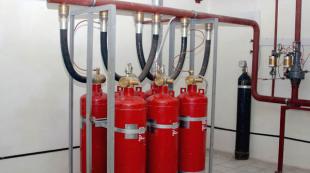
Modular gas fire extinguishing systems, in simple terms, are cylinders equipped with a gas lock (shut-off device) and a siphon tube. Inside contains GOTV. Gases, which are usually used in such systems, can be divided into two groups:
 Freons or inhibitors. They perform the function of slowing down the combustion process, which is due to chemical reactions, in particular, the decomposition of substances, during which the formation of free radicals occurs. Modular gas fire extinguishing systems operate in a similar way when they enter a fire. Such chemical reactions help to slow down combustion. The effectiveness of freons is noticeably lower than that of compressed gases.
We watch the video, the principle of the system:
Gases with the ability to dilute the atmosphere. Modular gas fire extinguishing systems with such filling operate according to the principle of creating conditions under which the maintenance of combustion will become impossible. It means that the permissible amount of oxygen in the atmosphere to continue the fire is at least 12%. A modular installation with gas fire extinguishing systems just contribute to a change in this amount of oxygen in a smaller direction. Such systems use compressed gases such as argon, inergen, nitrogen.
In the first group, modular gas-type fire extinguishing installations with freons, which are ozone-friendly, were especially popular. These include: Freon 23, Freon 227 ea, Freon 125. The first two options are allowed for use at objects where people are located.
Features and differences from analogues
Modular installations with a gas fire extinguishing system system in addition to the main structural elements have such a unit as mass control. It can be built-in or external, its main function is to control the level of the substance inside the container as it is used. The locking and starting device, which is equipped with modular gas-type installations with fire extinguishing systems, is responsible for the implementation of the following features:
- Retention in a gas cylinder in a compressed form;
- Monitoring the values \u200b\u200bof the working pressure in the system;
- Operation of the device if necessary;
- Protection of the module from deformation as internal pressure increases.
The gas fire extinguishing system module is connected to the device that is responsible for the start parameters. Most often, Gamma 01 or URP-7 devices are used for this. If the mass of the substance inside the cylinder decreases, falling below the normal value, the alarm will sound.
 The module with a gas-type fire extinguishing system is protected from exposure to high levels of pressure. In this case, the substance is released through the membrane of the safety device.
A module with a gas fire extinguishing system has several advantages:
- Preservation of the object from additional damage during the localization of the source of fire;
- The absence of harmful substances during the decomposition of GOTV;
- Quite high rate of fire extinguishing;
- Combustion products, together with the residues of GOTV, are quickly removed from the premises, it is enough to ventilate it.
But the module with a gas-type fire extinguishing system has some disadvantages. For example, the need to seal the premises and the inability to use such equipment outdoors.
Manufacturers Overview
One of the leaders is Impulse 20 gas type module for Brand fire extinguishing. This is a compact installation that successfully competes with large batteries to localize the source of fire. Inside the cylinder, this gas-type fire extinguishing module contains exclusively inhibitors; another type of gas is not intended to be used. With it, you can put out fires of different classes, in particular, A, B, C. And in addition to this, and electrical equipment under voltage.
Watch a video about the Impulse model:
The MPA nvc1230 gas fire extinguishing module can be used as self device and as a unit in the battery fire equipment. The capacity of the cylinders varies from 13.4 to 100 liters. These devices are of high quality and reliable design.
As an alternative, you can pay attention to the module of the gas fire extinguishing method MPA NVC1230. Devices of this type are distinguished by the ability to pick up the cylinder of the required parameters. The manufacturer offers a wide range of designs with different cylinder capacities.
Installation work and their cost
As a rule, the supplier company or the manufacturer, in addition to providing equipment, including the gas extinguishing method module, is also involved in the installation of fire systems at the facility. The cost depends on the area of \u200b\u200bthe room, as well as on the number of components of the battery. Installation of such installations can cost 300,000 rubles. and higher.
 If you plan to install equipment such as a gas fire extinguishing module, its price varies significantly depending on the brand, which should be taken into account. For example, an IHP of type Impulse-20 will cost about 77,000 rubles. The MGPT-65-60-50-P-01 model is much cheaper - about 50,000 rubles.
The MGP gas fire extinguishing module after refueling can last for a rather long time - up to 10 years. But this is only if the operating conditions of such equipment were observed. In order for the cylinder to last long enough, it is recommended to adhere to several rules:
As a minimum, during the monthly maintenance of the device, the pressure inside the cylinder is monitored. At the same time, IHL weight and room temperature are also controlled. To determine which values \u200b\u200bcorrespond to the norm, you should study the operating instructions for the cylinder. If noticeable changes in these parameters are observed, then the device is given for maintenance. In the event of a spontaneous triggering of the switchgear, which is likely only if the pressure exceeds the normal level, the device is also given for servicing and refueling.
Thus, the operation of the module under acceptable conditions will ensure the long-term service of this type of equipment. A correctly selected fire extinguishing cylinder in accordance with the area of \u200b\u200bthe room will allow in case of a dangerous situation to quickly localize the source of fire. The design of the module provides for a number of solutions in case of violation of the pressure level (in particular, triggering of the air flow switch), which avoids deformation of the cylinder. However, differences in the values \u200b\u200bof this parameter have a negative effect on the unit itself, if repeated regularly.
The recent major fires and technological disasters with significant material losses and human casualties make us pay attention to the significance and quality of fire prevention and suppression measures. When organizing fire protection at facilities, constructive and engineering solutions must be provided for saving human lives and material values.
Effective fire protection of objects for various purposes is impossible without the use of automatic fire extinguishing installations (APT). The positive experience of their application has led to the fact that in our country and abroad the number of anti-inflammatory drugs is constantly growing.
Depending on the type of extinguishing agent, ATP are divided into:
- water
- foamy
- gas
- powder
- gas aerosol.
It should be noted that there is no universal fire extinguishing installation. Each of the above fire extinguishing installations has its advantages and disadvantages.
Gas extinguishing installations (UGP) At present, they are increasingly used for fire protection of premises and technological equipment. When protecting single rooms, these installations have a comparatively higher cost compared to other installations; however, it is most preferable to use gas fire extinguishing to protect expensive property in relatively tight rooms. Fire extinguishing gas effectively extinguishes fires in a volumetric manner and easily penetrates into the shielded areas of the facility, where the supply of other OTV is difficult. After liquidation of the fire or unauthorized start-up of gas-fired gas extinguishing agent (GOTV), practically does not have a harmful effect on protected values \u200b\u200bin comparison with other extinguishing agents - water, foam, powder and aerosol, it is easily removed by ventilation. therefore automatic installations gas fire extinguishing (AUGP) is widely used to protect devices and control panels of nuclear power plants, computer centers and telecommunications equipment, libraries, archives, museums, bank valuables, a number of warehouses in closed rooms, as well as drying, painting, impregnation chambers, etc. More Moreover, for the protection of premises with computers, server rooms, archives, and others, fire prevention facilities are the only possible means of fire protection.
The choice of gas extinguishing agent should be made only on the basis of a feasibility study. All other parameters, including the efficacy and toxicity of GOTV, cannot be considered as determining for a number of reasons.
One of the most important tasks of using extinguishing gases is to ensure the safety of personnel in the protected premises.
According to the requirements of normative documents NPB 88, GOST R 50969, GOST 12.3.046, personnel safety is ensured by the preliminary evacuation of people before the supply of fire extinguishing gas by signals from sirens during the time delay intended for this. The minimum duration of a time delay for evacuation is determined by NPB 88 and is 10 s. The designer can increase this time taking into account the conditions of evacuation at the facility.
The safety of personnel in case of unauthorized supply of extinguishing gas to people depends on the concentration of this gas and the exposure time (exposure). Abroad, large-scale studies have been carried out to study the properties of modern extinguishing gases - freon 125, 227еа and several others. It has been convincingly shown that these gases are most safe when exposed to people at a concentration equal to or slightly greater than the extinguishing concentration.
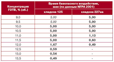
Information on the duration (time) of the safe human exposure to HFC 125 and HFC 227ea depending on the gas concentration is given in ISO 14520, NFPA 2001, as well as in the manual of VNIIPO “Means fire automatics. Application area. Choice of type ”, and are indicated in table 1. The exposure time in bold indicates the exposure time when the concentration exceeds the standard for extinguishing class A2 fires (computer centers, server centers, etc.). It follows that freon 125 and 227еа are capable of ensuring safe evacuation of personnel for at least 30 s not only at the standard fire extinguishing concentration (it is 9.8% vol. For freon 125 and 7.2% vol. For freon 227еа), but also when it is exceeded by 38% for HFC 125 and by 67% for HFC 227 ea. Thus, freon 125 and 227 ea are more preferred and effective as the main gas extinguishing agents for
protection of premises in which personnel can be present continuously during working hours, providing fire fighting at concentrations of only 10 and 7%, respectively. Freons belong to liquefied gases, which allows them to be compactly placed in the volume of the container in significant quantities. In addition, the heat resistance of HFC 125 is a preferred property for fighting fires of smoldering materials.
As part of the technological equipment of AUGP, freons are contained in gas fire extinguishing modules under pressure of a propellant. As a propellant, domestic standards NPB-88 and GOST R 50969 suggest the use of nitrogen or dried air. In advanced domestic equipment, only nitrogen is used. The reason is that the dried air reduces the extinguishing efficiency, entering the protected room after the refrigerant. In addition, water vapor in dry air impairs the storage conditions of the freon.
Carbon dioxide (CO2) is traditionally used to protect industrial facilities (diesel, LVZH warehouses, compressor, etc.). Such objects are characterized by intensive fire development due to the presence of a class B fire load in accordance with GOST 27331 ( diesel fuel, oils, gasoline, etc.), cables, electrical equipment under high voltage, as well as a number of other features.
Carbon dioxide (CO2) successfully extinguishes such fires in compliance with the increased safety factor established by the standards. This coefficient determines the level of excess of the regulatory concentration over the minimum (Smok) required to extinguish a fire in laboratory conditions. For CO2, the indicated coefficient is 1.7. According to NPB 88, the safety factor for chladones is 1.2, which is 40% less than for CO2.
A significant excess of the normative CO2 concentration over Smok creates the conditions for eliminating repeated sunburns and reduces the dependence of fire extinguishing efficiency on the tightness of the facility.
In addition, CO2 is an ideal gas for extinguishing fires of smoldering materials, as treats heat-resistant gases and does not emit products of thermal decomposition.
It is known that CO2 extinguishing creates an atmosphere unsuitable for breathing. Therefore, our experts recommend the use of CO2 only in rooms where personnel are absent (spray booths, etc.) or may be present only periodically, for example, for visual inspection, operational adjustment of equipment, etc.
In the latter case, personnel safety is ensured by evacuation prior to gas supply. At such facilities, special attention should be paid to the failure-free operation of sirens, staff training, the availability of free evacuation routes, and a number of other organizational and technical measures.
The choice of extinguishing agent and fire extinguishing method determines the type of fire extinguishing installation and its technological equipment.
The cost of each of the GOTVs is significantly different from each other. At the same time, knowing only the price of 1 kg of gas extinguishing agent, it is impossible to estimate the cost of fire protection of 1 m 3 volume. We can only say unequivocally that in our country and abroad the protection of 1 m 3 of volume with GOTV N 2, Ar and Inergen is more than 1.5 times higher in cost compared to other gas extinguishing agents. Because N 2, Ar and Inergen are stored in gas extinguishing modules in a gaseous state, which requires more gas extinguishing modules than other GOTVs.
There are two methods of gas fire extinguishing: volumetric and locally volumetric. In the vast majority of cases, the volumetric method is used. A method that is local in volume from an economic point of view is advantageous only if the volume of the room is more than 6 times the conditionally allocated volume occupied by equipment subject to protection by UGP. In this case, the fire extinguishing method that is local in volume is more economical than the volume fire method.
UGP are of two types: centralized (station) and modular installation. With fire protection of one room at the facility, of course, a modular UGP is installed. If it is necessary to protect 2 or more rooms, the choice of the type of gas fire extinguishing installation as well as the extinguishing method is determined primarily by economic feasibility. The main selection criteria are:
- Availability of a free room in which you can place a fire extinguishing station that meets regulatory requirements.
- The number of protected premises at one facility;
- Values \u200b\u200bof protected volumes.
- The remoteness of the premises from the fire extinguishing station.
The main components of gas treatment are: gas extinguishing agent, gas fire extinguishing modules (gas fire extinguishing), distribution devices (for centralized installation), nozzles and piping.
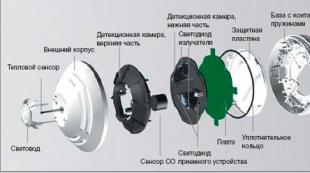
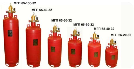
The most complex product that determines the reliability of the automatic fire extinguishing installation is the gas fire extinguishing module. The latter is a cylinder with a locking-starting device (ZPU).
In operation, cylinders with a capacity of up to 100 liters are preferred, as they are convenient for transportation and installation, are not subject to registration with the Rostekhnadzor authorities and they do not have additional stringent requirements for placement and maintenance in accordance with PB 03-576-03. Cylinders with a capacity of more than 100 liters have restrictions on the place of their installation, in addition, higher requirements are imposed on the persons performing their maintenance.
![]()
An important place in the design of the module is occupied by a high pressure cylinder. The main criterion for its assessment is the coefficient of weight return, which characterizes its metal consumption and the technological level of manufacture. The larger the value of this coefficient, the more perfect the design of the vessel. For the manufacture of modern cylinders of light high-pressure cylinders, high-strength alloy steel of high uniformity of the AKS class (atmospheric, corrosion-resistant) is used, which has a higher (2–3 times) corrosion resistance and increased adhesion to paint coatings in relation to other steels. The presence of an internal coating in the form of a phosphating primer and VK high-elastic glue provides additional protection for the cylinder against aggressive environments and increases the corrosion resistance by another 1.5–2 times. Rust is not formed both inside and outside the cylinders. Due to this property, for such modules a fifteen-year term of operation is established until the first technical examination. The estimated service life of the cylinders is at least 30 years and can be increased by the results of operation.
Currently it is allowed to apply in Russia (they have certificates fire safety) gas fire extinguishing modules of more than 10 domestic and foreign firms. The gas fire extinguishing modules currently used in the gas treatment plant for storage of HFC 125, HFC 318C, HFC 227ea can be divided into two groups according to operating pressure. The first group should include modules with operating pressures up to 4.0 - 4.2 MPa. As a rule, these modules are intended for use only in modular UGP. The second group includes MHPs having a working pressure of up to 6.5 MPa. These modules are used both in centralized and in modular installation of gas fire extinguishing.
With all its variety of designs, ZPU modules can be divided into three principal types:
- locking and starting devices having a destructive element (membrane, glass flask, etc.) and a squib;
- locking and starting devices having a locking member in the form of a valve that opens after the igniter is triggered;
- locking and starting devices having an electromagnetic start.
A module’s locking and starting device usually contains three main components: a locking element, a starting element and a drive. In domestic and foreign practice, two types of locking organs are used: valve and membrane. The former have a split valve-seat section. When activated, the valve moves away from the seat, freeing the outlet. Membrane nodes do not contain a movable detachable section, they open by breaking the locking element. Due to the presence of a large diameter detachable cross-section in the valve assembly, it is fundamentally less tight than the membrane assembly. In conditions of increased vibration and shock loading, the tightness of the valve assembly is further deteriorated. The ZPU drive, as a rule, contains kinematic mechanisms: pistons, valves, levers on the axes and other movable elements, which must be rotated or moved to ensure operation. The starting element of the ZPU is usually electromagnets or squibs. The latter are most widely used, since they do not contain moving elements (all energy is concentrated in their charge) and do not require maintenance. At the facility equipped with a gas fire extinguishing system, the modules can be in standby mode without triggering a very long period (10 years or more). Under these conditions, the ZPU of the module is immobilized, it undergoes the processes of aging, corrosion, pollution, acidification. The module must provide not only long-term storage without loss of extinguishing gas, but also trouble-free start-up at the end of its service life, when an object “grew old” together with the module and the likelihood of a fire increased. Movable starting and driving mechanisms, shut-off valves, which have never been moved during a long period of operation, may lose their actuation ability if they are not subjected to cleaning and training. Foreign standards provide for the training of the solenoid at least once every three months.
At present, devices are manufactured in Russia in which the locking element is made in the form of a discontinuous element, which is a special gas impermeable and one-piece jumper. No drive is required in the switchgear, - the design is a two-link (locking element - starting element). As a starting element, a special pyro cartridge was used, the pyro charge of which is hermetically separated from the environment by a stainless steel case, guaranteed to remain operational with a probability of 0.999 for 17 years. To increase reliability, the squib has two galvanically isolated spirals. To bring it into action, a low-power starting pulse is required in comparison with an electromagnet, which produces almost any control device.
An analysis of the global trend shows that most foreign firms produce gas fire extinguishing modules with electromagnetic start-up of ZPU. This is caused by the following:
- An electromagnet, as a rule, is triggered at a current of less than 0.5 A compared to a squib with a trip current of more than 1.0 A.
- The design of the ZPU with electromagnetic start-up allows for pneumatic start-up, which is especially important when a large number of IHLs are triggered. In this case, up to 10 modules can be started simultaneously from one electromagnet.
- After the triggering of the IHL, there is no need to purchase components (membranes, squibs, etc.) to restore the functionality of the modules belonging to the 1st and 2nd type. This is especially important for organizations operating the modules away from the company that manufactured them, or a specialized service center.
- A switchgear with an electromagnet can always be checked for reliable operation. Because in the event of a triggering of a ZPU belonging to the first type, after replacing the destroyed locking element and the squib, it becomes an almost new product. Moreover, in practice there were cases when, after the pyro cartridge was triggered, the module was not launched. Unfortunately, in Russia, in contrast to the global trend, more than half of the gas fire extinguishing modules approved for installation in gas treatment facilities have the 1st and 2nd types of locking and starting devices.
The IHL discussed above allows protecting, as a rule, a volume not exceeding 200 m 3. Therefore, to protect rooms with a volume of more than 2000 m 3, a sufficiently large number of IHL (batteries) is required, which reduces the reliability of the IHL in general. In addition, a large free area is required for installing gas extinguishing modules.
The technical and economic comparison showed that for the protection of premises with a volume of more than 2000 m 3 in gas treatment plants, it is more advisable to use isothermal modules for liquid carbon dioxide (MIZU).
MIZHU consists of an isothermal storage tank for CO 2, with a capacity of 3,000 liters to 25,000 liters, a locking and starting device, CO 2 quantity and pressure control devices, refrigeration units and a control cabinet.
Of the UGPs available on our market that use isothermal tanks for liquid carbon dioxide in their composition, MIZHU of Russian production technical specifications superior to foreign products. Foreign-made insulated tanks must be installed in a heated room. MIZHU of domestic production can be operated at ambient temperature up to minus 40 degrees, which allows installing isothermal tanks outside buildings. In addition, unlike foreign products, the design of the Russian MIZHU allows the supply of CO2 to the protected room, dosed by weight.
Freon nozzles
For uniform distribution of GOTV in the volume of the protected space, nozzles are installed on the distribution pipelines of UGP.
Nozzles are installed on the outlet openings of the pipeline. The design of the nozzles depends on the type of gas supplied. For example, to supply Freon 114B2, which under normal conditions is a liquid, previously used two-jet nozzles with impact jets. Currently, such nozzles are recognized to be ineffective. Regulatory documents recommend replacing them with jack-off or centrifugal nozzles providing a fine spray of type 114B2 freon.
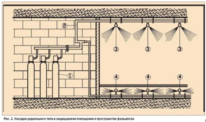
To supply freon type 125, 227ea and CO2, radial nozzles are used. In such nozzles, the flows of gas entering the nozzles and exiting jets of gas are approximately perpendicular. Nozzles of radial type are divided into ceiling and wall. Ceiling nozzles can deliver gas jets to the sector with an angle of 360 °, wall nozzles - about 180 °.
An example of the use of radial-type ceiling nozzles as part of AUGP is shown in Fig. 2.
The placement of nozzles in the protected room is carried out in accordance with the technical documentation of the manufacturer. The number and area of \u200b\u200bnozzle outlet openings is determined by hydraulic calculation, taking into account the flow coefficient and the spray map specified in the technical documentation for the nozzles.
AUGP pipelines are made of seamless pipes, which ensures the preservation of their strength and tightness in dry rooms for a period of up to 25 years. Applied pipe connection methods - welded, threaded or flanged
To maintain the flow characteristics of piping for a long service life, nozzles should be made of corrosion-resistant and durable materials. Therefore, leading domestic firms do not use nozzles made of coated aluminum alloys, but use only brass nozzles.
The right choice of UGP depends on many factors.
Consider the main of these factors.
Fire protection method.
UGP are intended for creation in the protected room (volume) of the gas environment not supporting combustion. Therefore, there are two methods of fire extinguishing: volumetric and local-volumetric. The vast majority of the volumetric method. A method that is local in volume from an economic point of view is advantageous when the equipment to be protected is installed in a large area, which, according to regulatory requirements, does not need to be fully protected.
NPB 88-2001 provides regulatory requirements for the local volumetric fire extinguishing method for carbon dioxide only. Based on these regulatory requirements, it follows that there are conditions under which a fire extinguishing method that is local in volume is more economically viable than volumetric. Namely, if the volume of the room is 6 times or more larger than the conditionally allocated volume occupied by the equipment to be protected by the anti-terrorist operation, then in this case the fire extinguishing method that is local in volume is more economical than the volume fire.
Gas extinguishing agent.
The choice of a gas extinguishing agent should be made only on the basis of a feasibility study. All other parameters, including the efficacy and toxicity of GOTV, cannot be considered as determining for a number of reasons.
Any of the approved GOTV allowed for use is quite effective and the fire will be eliminated if a standard fire extinguishing concentration is created in the protected volume.
An exception to this rule is the extinguishing of smoldering materials. Studies conducted at the Federal State Institution VNIIPO EMERCOM of Russia under the leadership of A.L. Chibisova showed that a complete cessation of combustion (flame and smoldering) is possible only when three times the standard amount of carbon dioxide is supplied. This amount of carbon dioxide can reduce the oxygen concentration in the combustion zone below 2.5% vol.
According to the regulatory requirements in force in Russia (NPB 88-2001), it is forbidden to release a gas fire extinguishing substance into the room if there are people there. And this restriction is correct. Statistics on the causes of deaths in fires show that more than 70% of deaths were caused by poisoning from combustion products.
The cost of each of the GOTVs is significantly different from each other. At the same time, knowing only the price of 1 kg of gas extinguishing agent, it is impossible to estimate the cost of fire protection of 1 m 3 volume. One can only say unequivocally that the protection of 1 m 3 of volume with GOTV N 2, Ar and Inergen is 1.5 times more expensive and more expensive than other gas extinguishing agents. This is because the listed GOTVs are stored in gas extinguishing modules in a gaseous state, which requires a large number of modules.
Type of gas fire extinguishing installation.
UGPs come in two types: centralized and modular. The choice of the type of gas fire extinguishing installation depends, firstly, on the number of rooms to be protected at one facility, and secondly, on the availability of free space in which a fire extinguishing station can be placed.
When protecting at the same object 3 or more rooms located from each other at a distance of no more than 100 m, from an economic point of view, centralized gas treatment facilities are preferable. Moreover, the cost of the protected volume decreases with an increase in the number of rooms protected from one fire extinguishing station.
At the same time, a centralized gas treatment facility as compared to a modular one has a number of drawbacks, namely: the need to fulfill a large number of requirements of NPB 88-2001 for a fire extinguishing station; the need to lay pipelines in the building from the fire extinguishing station to the protected premises.
Fire extinguishing modules and batteries.
Gas extinguishing modules (IHF) and batteries are the main element of a gas extinguishing installation. They are designed to store and release GOTV in a protected room.
IHL consists of a cylinder and a locking-starting device (ZPU). Batteries, as a rule, consist of 2 or more gas fire extinguishing modules combined by a single factory-made collector. Therefore, all the requirements that apply to IHL are similar for batteries.
Depending on the gas extinguishing agent used in the gas pressure control device, the IHL must satisfy the requirements listed below.
IHL seasoned with freon of all grades should ensure that the GOTV release time does not exceed 10 s.
The design of gas fire extinguishing modules fueled with СО 2, N 2, Ar and Inergen should ensure that the GOTV release time does not exceed 60 s.
During the operation of the IHL, the mass control of the charged GOTV should be ensured.
The mass control of HFC 125, HFC 318C, HFC 227ea, N 2, Ar and Inergen is controlled by a manometer. If the pressure of the propellant in the cylinders with the above-listed freons decreases by 10%, and N 2, Ar and Inergen by 5% of the nominal IHL should be sent for repair. The difference in pressure loss is caused by the following factors:
With a decrease in the pressure of the propellant, the mass of the freon in the vapor phase is partially lost. However, this loss is not more than 0.2% of the initially loaded mass of freon. Therefore, a pressure limitation of 10% is caused by an increase in the time of GOTV release from the gas treatment unit as a result of a decrease in the initial pressure, which is determined based on the hydraulic calculation of the gas fire extinguishing installation.
N 2, Ar and Inergen are stored in compressed gas fire extinguishing modules. Therefore, a decrease in pressure of 5% of the initial value is an indirect method of losing the GOTV mass by the same value.
The control of the mass loss of the GOTV displaced from the module under the pressure of its own saturated vapors (HFC 23 and CO 2) should be carried out by the direct method. Those. the gas fire extinguishing module, charged with Freon 23 or CO 2, must be installed on the weighing device during operation. At the same time, the weighing device should provide control of the mass loss of the gas extinguishing agent, and not the total mass of the GOTV and the module, with an accuracy of 5%.
The presence of such a weighing device provides that the module is mounted or suspended on a durable elastic element, the movements of which change the properties of the load cell. An electronic device responds to these changes, which gives an alarm signal when the load cell parameters change above a set threshold. The main disadvantages of the strain gauge device are the need to ensure the free movement of the cylinder on a strong metal-intensive structure, as well as the negative influence of external factors - connecting pipelines, periodic shocks and vibration during operation, etc. The metal consumption and dimensions of the product increase, installation problems increase.
In the modules MPTU 150-50-12, MPTU 150-100-12, a high-tech method for monitoring the safety of GOTV is used. An electronic mass control device (UKM) is integrated directly into the locking-starting device (ZPU) of the module.
All information (GOTV mass, calibration date, service date) is stored in the UKM storage device and, if necessary, can be displayed on a computer. For visual control, the module’s switchgear is equipped with an LED that gives signals about normal operation, reduction of the GOTV mass by 5% or more, or UKM malfunctions. At the same time, the cost of the proposed gas mass control device in the module is much less than the cost of a tensometric weighing device with a control device.
The module isothermal for liquid carbon dioxide (MIZhU).
MIZHU consists of a horizontal storage tank for СО 2, a locking and starting device, devices for monitoring the amount and pressure of СО 2, refrigeration units and a control panel. Modules are designed to protect rooms up to 15 thousand m 3. The maximum capacity of MIZHU is 25 tons of СО 2. As a rule, the working and reserve stock of CO 2 is stored in the module.
An additional advantage of MIZHU is the possibility of installing it outside the building (under a canopy), which can significantly save production space. In a heated room or a warm block box, only MIZU control devices and UGP switchgears (if any) are installed.
IHL with a cylinder capacity of up to 100 l, depending on the type of combustible load and refueling GOTV, protect the room with a volume of not more than 160 m 3. To protect larger rooms, installation of 2 or more modules is required.
The technical and economic comparison showed that for the protection of premises with a volume of more than 1,500 m 3 in gas treatment plants, it is more expedient to use isothermal modules for liquid carbon dioxide (MIZU).
Nozzles.
Nozzles are designed for uniform distribution of GOTV into the volume of the protected room.
The placement of nozzles in the protected room is carried out in accordance with the technical specifications of the manufacturer. The number and area of \u200b\u200bnozzle outlet openings is determined by hydraulic calculation, taking into account the flow coefficient and the spray map specified in the technical documentation for the nozzles.
The distance from the nozzles to the ceiling (ceiling, false ceiling) should not exceed 0.5m when using all GOTV, except for N 2.
Pipe routing.
The piping in the protected room, as a rule, should be symmetrical with equal distance of nozzles from the main pipeline.
Piping installations are made of metal pipes. The pressure in the pipelines of the installation and the diameters are determined by hydraulic calculation according to the methods agreed upon in the established order. Pipelines must withstand pressure during testing for strength and tightness of at least 1.25 Rrab.
When using freon as GOTV, the total volume of pipelines, including the collector, should not exceed 80% of the liquid phase of the working stock of the freon in the installation.
Tracing the distribution piping of plants using freon should only be done in a horizontal plane.
When designing centralized plants using chladones, attention should be paid to the following points:
- connect the main pipeline of the room with the maximum volume should be closer to the battery with GOTV;
- when connecting batteries to the station collector in series with the main and reserve stock, the farthest from the protected premises should be the main stock from the condition of the maximum output of freon from all cylinders.
Selection and calculation of a gas fire extinguishing system.
The correct choice of a gas fire extinguishing system for gas-fired gas treatment depends on many factors. Therefore, the aim of this work is to show the main criteria that affect the optimal choice of hydraulic fracturing and the principle of its hydraulic calculation.
The following are the main factors that influence the optimal selection of UGP. Firstly, the type of combustible load in the protected room (archives, stock storages, electronic equipment, technological equipment, etc.). Secondly, the value of the protected volume and its leakage. Thirdly, the type of gas fire extinguishing agent GOTV. Fourth, the type of equipment in which GOTV should be stored. Fifth, the type of UGP: centralized or modular. The latter factor can take place only if it is necessary to fire protection of two or more rooms at one facility. Therefore, we consider the mutual influence of only four of the above factors. Those. under the assumption that the facility requires fire protection of only one room.
Of course, the right choice of PFM should be based on optimal technical and economic indicators.
It should be especially noted that any of the approved GOTVs eliminates the fire regardless of the type of combustible material, but only when a standard extinguishing concentration is created in the protected volume.
We will evaluate the mutual influence of the above factors on the technical and economic parameters of UGP from the condition that the following GOTVs are allowed for use: HFC 125, HFC 318C, HFC 227еа, HFC 23, СО 2, N 2, Ar and a mixture (N 2, Ar and CO 2), which has the trademark "Inergen".
According to the storage method and GOTV control methods in the IHP gas fire extinguishing modules, all gas extinguishing substances can be divided into three groups.
The 1st group includes HFC 125, HFC 318C and HFC 227еа. These freons are stored in MHP in a liquefied form under the pressure of a propellant, most often nitrogen. Modules with the listed chladones, as a rule, have a working pressure not exceeding 6.4 MPa. The control of the amount of freon during the operation of the installation is carried out by a pressure gauge installed on the IHL.
Freon 23 and CO 2 make up the 2nd group. They are also stored in a liquefied form, but are displaced from the IHL under the pressure of their own saturated vapors. The operating pressure of the modules with the specified GOTV must have a working pressure of at least 14.7 MPa. During operation, the modules must be installed on weighing devices that provide continuous control of the mass of HFC 23 or CO 2.
The 3rd group includes N 2, Ar and Inergen. GOTV data is stored in the IHL in a gaseous state. Further, when we evaluate the advantages and disadvantages of GOTV from this group, only nitrogen will be considered. This is due to the fact that N2 is the most effective GOTV (has the lowest fire extinguishing concentration and at the same time the lowest cost). The mass control of the GOTV of the 3rd group is carried out by a manometer. N 2, Ar or Inergen are stored in modules at a pressure of 14.7 MPa or more.
Gas extinguishing modules, as a rule, have a cylinder capacity not exceeding 100 l. Modules with a capacity of more than 100 l according to PB 10-115 are subject to registration with the Gosgortekhnadzor of Russia, which entails a fairly large number of restrictions on their use in accordance with the specified rules.
An exception is isothermal modules for liquid carbon dioxide MIZHU with a capacity of from 3.0 to 25.0 m3. These modules are designed and manufactured for storage in gas fire extinguishing installations of carbon dioxide in quantities exceeding 2500 kg or more. MIZHU are equipped with refrigeration units and heating elements, which allows maintaining pressure in an isothermal tank in the range of 2.0 - 2.1 MPa at an ambient temperature of minus 40 to plus 50 degrees. FROM.
Let's look at examples of how each of the 4 factors affects the technical and economic indicators of UGP. The mass of GOTV was calculated according to the method described in NPB 88-2001.
Example 1 It is required to protect electronic equipment in a room of 60 m 3. The room is conditionally sealed. Those. K2 \u003d 0. The calculation results are summarized in table. 1.
Table 1
The economic justification of the table in specific figures has a certain difficulty. This is due to the fact that the cost of equipment and GOTV for firms - manufacturers and suppliers has different costs. However, there is a general trend in that the cost of the gas fire extinguishing module increases with increasing capacity of the cylinder. The cost of 1 kg of CO 2 and 1 m 3 N 2 are close in price and two orders of magnitude less than the cost of freon. Table analysis 1 shows that the cost of UGP with HFC 125 and CO 2 are comparable in magnitude. Despite the significantly higher cost of HFC 125 compared with carbon dioxide, the total price of HFC 125 - MHP with a cylinder of 40 l will be comparable to or even slightly lower than the set of carbon dioxide - MHP with an 80 l tank - weighing device. It is unambiguously possible to state a significantly higher cost of hydrogen-carbon dioxide with nitrogen in comparison with the two previously considered options. Because 2 modules with maximum capacity are required. It will take more space to accommodate 2 modules in a room and, of course, the cost of 2 modules of 100 l will always be more than a 80 l module with a weighing device, which, as a rule, is 4-5 times less than the price of the module itself.
Example 2. The parameters of the room are similar to example 1, but it is required to protect not the electronic equipment, but the archive. The calculation results similarly to the 1st example are presented in table. 2 are summarized in table. 1.
table 2
Based on the analysis of the table. 2, it can be said unequivocally, and in this case, gas-fired gas treatment plants with nitrogen are significantly higher in cost than gas fire extinguishing installations with HFC 125 and carbon dioxide. But unlike the first example, in this case it can be more clearly noted that carbon dioxide is the least expensive. Because with a relatively small difference in cost between an IHL with a cylinder, the capacity of 80 l and 100 l, the price of 56 kg of HFC 125 significantly exceeds the cost of the weighing device.
Similar dependencies will be observed if the volume of the protected premises increases and / or its leakage increases. Because all this causes a general increase in the amount of any type of GOTV.
Thus, only on the basis of 2 examples it can be seen that it is possible to choose the optimal gas protection factor for fire protection of a room only after considering at least two options with various kinds READY
However, there are exceptions when a gas treatment facility with optimal technical and economic parameters cannot be applied due to certain restrictions imposed on gas extinguishing agents.
Such restrictions, first of all, include the protection of critical facilities in an earthquake-prone zone (for example, nuclear power facilities, etc.), where installation of modules in earthquake-resistant frames is required. In this case, the use of freon 23 and carbon dioxide is excluded, since the modules with these GOTV should be installed on weighing devices that exclude their rigid fastening.
In case of fire protection of premises with constantly present personnel (air traffic control rooms, halls with control panels of nuclear power plants, etc.), GOTV toxicity limits are imposed. In this case, the use of carbon dioxide is excluded, since the volumetric extinguishing concentration of carbon dioxide in the air is fatal to humans.
When protecting volumes of more than 2000 m 3 from the economic point of view, the most acceptable is the use of carbon dioxide charged at MIZHU, in comparison with all other GOTV.
After conducting a feasibility study, the amount of GOTV required to eliminate the fire and the preliminary amount of IHL become known.
Nozzles must be installed in accordance with the spray cards specified in the technical documentation of the nozzle manufacturer. The distance from the nozzles to the ceiling (ceiling, false ceiling) should not exceed 0.5 m when using all GOTV, with the exception of N 2.
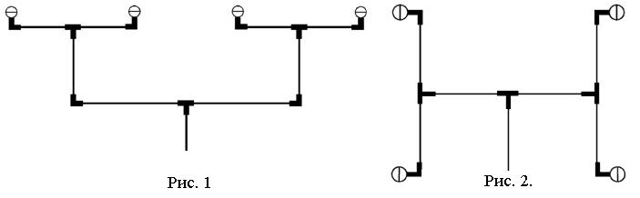
Pipe wiring, as a rule, should be symmetrical. Those. nozzles should be equidistant from the main pipeline. In this case, the GOTV flow rate through all nozzles will be the same, which will ensure the creation of a uniform fire extinguishing concentration in the protected volume. Typical examples of symmetrical piping are shown in fig. 1 and 2.
When designing the piping, the correct connection of the discharge pipelines (rows, bends) from the main pipeline should also be taken into account.
A cross-shaped connection is possible only if the GOTV flow rate G1 and G2 are equal in magnitude (Fig. 3).
If G1? G2, then the opposite connections of the rows and branches with the main pipeline must be spaced in the direction of the GOTV movement by a distance L exceeding 10 * D, as shown in Fig. 4. Where D is the internal diameter of the main pipeline.

There are no restrictions on the spatial connection of pipes when designing the piping of gas-pressure treatment units when using GOTV belonging to the 2nd and 3rd groups. And for the pipe wiring of gas treatment units with GOTV of the 1st group there are a number of restrictions. This is caused by the following:
When supercharging HFC 125, HFC 318C or HFC 227еa in MHP with nitrogen to the required pressure, nitrogen partially dissolves in the listed HFCs. Moreover, the amount of dissolved nitrogen in freons is proportional to the boost pressure.
After opening the locking and starting device of the fire protection module of the gas fire extinguishing module under the pressure of the propellant gas, the freon with partially dissolved nitrogen flows through the pipe wiring to the nozzles and through them enters the protected volume. In this case, the pressure in the system (modules - pipe wiring) decreases as a result of the expansion of the volume occupied by nitrogen in the process of displacing the freon, and the hydraulic resistance of the pipe wiring. A partial release of nitrogen from the liquid phase of the freon occurs and a two-phase medium is formed (a mixture of the liquid phase of the freon - nitrogen gas). Therefore, a number of restrictions are imposed on the pipe wiring of a gas treatment unit using the 1st GOTV group. The main point of these restrictions is to prevent stratification of the two-phase medium inside the pipe wiring.
During the design and installation, all connections to the UGP pipe wiring should be performed as shown in Fig. 5a, 5b and 5c
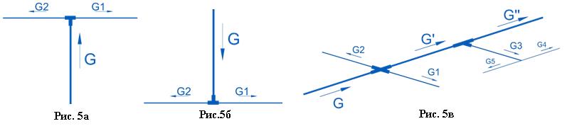
and it is forbidden to perform in the forms shown in Fig. 6a, 6b, 6c. In the figures, the arrows show the direction of the GOTV flow through the pipes.

In the process of designing a CGP in axonometric form, a pipe wiring diagram, the length of the pipes, the number of nozzles and their elevations are performed. For determining inner diameter pipes and the total area of \u200b\u200bthe outlet openings of each nozzle, it is necessary to perform a hydraulic calculation of the gas fire extinguishing installation.
Management of automatic gas fire extinguishing installations
When choosing the best option for controlling automatic gas fire extinguishing installations, it is necessary to be guided by the technical requirements, features and functionality of the protected objects.
The main schemes for constructing gas fire extinguishing installation control systems:
- autonomous gas fire extinguishing control system;
- decentralized gas fire extinguishing control system;
- centralized gas fire extinguishing control system.
Other options are derived from these typical schemes.
To protect local (separate) rooms on one, two and three directions of gas fire extinguishing, as a rule, the use of autonomous gas fire extinguishing installations is justified (Fig. 1). An autonomous gas fire extinguishing control station is located directly at the entrance to the protected room and controls both threshold fire detectors, light or sound alerts, and devices for remote and automatic start-up of a gas fire extinguishing installation (GST). The number of possible directions for gas fire extinguishing according to this scheme can reach from one to seven. All signals from an autonomous gas fire extinguishing control station go directly to the central control room at a remote display station.
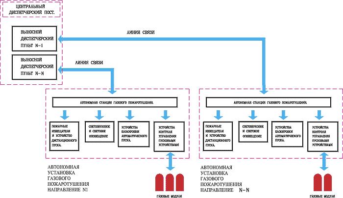
Fig. 1.Autonomous gas fire extinguishing control installations
The second typical scheme is a decentralized gas fire extinguishing control scheme, shown in Fig. 2. In this case, an autonomous gas fire extinguishing control station is integrated into an existing and existing integrated facility security system or newly designed. Signals from an autonomous gas fire extinguishing control station are sent to address blocks and control modules, which then transmit information to a central control room at a central station fire alarm. A feature of decentralized gas fire extinguishing control is that when individual elements of the integrated security system of an object fail, an autonomous gas fire extinguishing control station remains in operation. This system allows you to embed in your system any number of directions of gas fire extinguishing, which are limited only by the technical capabilities of the fire alarm station itself.

Fig. 2.Decentralized management of gas fire extinguishing in several directions
The third scheme is a centralized control scheme for gas fire extinguishing systems (Fig. 3). This system applies when the requirements for fire safety are priority. The fire alarm system includes address-analog sensors that allow you to control the protected space with minimal errors and prevent false alarms. False alarms of the fire system occur due to contamination of ventilation systems, forced exhaust ventilation (smoke from the street), strong wind, etc. Prevention of false alarms in address-analog systems is carried out by monitoring the dust level of the sensors.
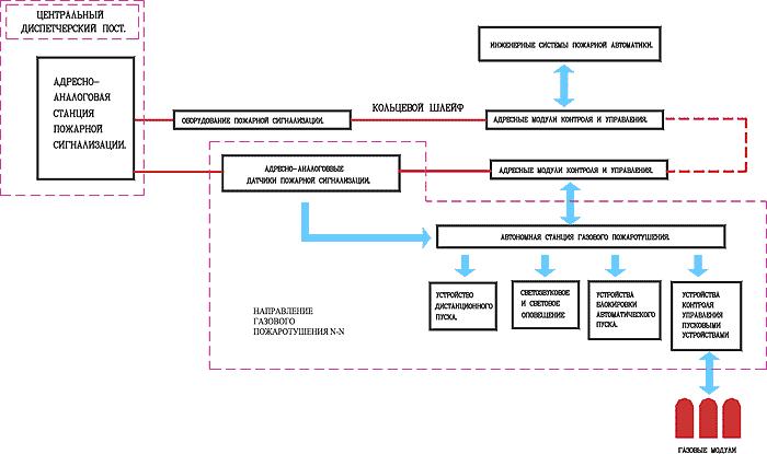
Fig. 3. Centralized management of gas fire fighting in several directions
The signal from the address-analog fire detectors arrives at the central fire alarm station, after which the processed data through the address modules and blocks is fed to an autonomous gas fire extinguishing control system. Each group of sensors is logically tied to its gas fire extinguishing direction. The centralized gas fire extinguishing control system is designed only for the number of station addresses. Take, for example, a station with 126 addresses (single-loop). We calculate the number of necessary addresses for maximum protection of the room. The control modules are automatic / manual, gas is supplied and the fault is 3 addresses plus the number of sensors in the room: 3 - on the ceiling, 3 - on the ceiling, 3 - under the floor (9 pcs.). We get 12 addresses to the destination. For a station with 126 addresses, these are 10 directions plus additional addresses for managing engineering systems.
The use of centralized gas fire extinguishing control leads to a rise in the cost of the system, but significantly increases its reliability, makes it possible to analyze the situation (control dustiness of sensors), and also reduces the level of costs for its maintenance and operation. The need to install a centralized (decentralized) system arises from the additional management of engineering systems.
In some cases, in centralized and decentralized gas extinguishing systems, fire extinguishing stations are used instead of a modular gas extinguishing installation. Their installation depends on the area and the specifics of the protected premises. In fig. 4 shows a centralized gas fire extinguishing system with a fire extinguishing station (OGS).

Fig. 4.Centralized gas fire extinguishing in several directions with a fire extinguishing station
The choice of the optimal installation of gas fire extinguishing depends on a large amount of source data. An attempt to summarize the most significant parameters of gas extinguishing systems and installations is presented in Fig. 5.

Fig. 5.Choosing the best option for installing gas fire extinguishing according to technical requirements
One of the features of AGPT systems in automatic mode is the use of analog address and threshold fire detectors as fire detection devices, when triggered, the fire extinguishing system is started, i.e. fire extinguishing agent release. And here it should be noted that the reliability of a fire detector, one of the cheapest elements of a fire alarm and fire extinguishing system, determines the operability of the entire expensive fire alarm system and, therefore, the fate of the protected facility! At the same time, the fire detector must satisfy two basic requirements: early detection of fire and the absence of false alarms. What determines the reliability of a fire detector as an electronic device? From the level of development, the quality of the element base, assembly technology and final testing. It can be very difficult for a consumer to understand the whole variety of detectors on the market today. Therefore, many are guided by the price and availability of a certificate, although, unfortunately, it is not a guarantee of quality today. Only a few fire detector manufacturers openly publish failure figures, for example, according to the Moscow manufacturer System Sensor Fair Detectors, the return on its products is less than 0.04% (4 products per 100 thousand). This, of course, is a good indicator and the result of multi-stage testing of each product.
Of course, only the address-analog system allows the customer to be absolutely confident in the operability of all its elements: smoke and heat sensors that monitor the protected room are constantly questioned by the fire extinguishing control station. The device monitors the status of the loop and its components, in case of a decrease in the sensitivity of the sensor, the station automatically compensates for it by setting the appropriate threshold. But when using addressless (threshold) systems, the breakdown of the sensor is not detected, and the loss of its sensitivity is not monitored. It is believed that the system is in working condition, but in reality the fire extinguishing control station in the event of a real fire will not work accordingly. Therefore, when installing automatic gas fire extinguishing systems, it is preferable to use address-analog systems. Their relatively high cost is offset by unconditional reliability and a qualitative reduction in the risk of fire.
Design of gas fire extinguishing installations.
In the general case, the working draft of the gas fire extinguishing installation consists of an explanatory note, a technological part, an electrical part (not considered in this work), a specification of equipment and materials and estimates (at the request of the customer).
Explanatory note
The explanatory note includes the following sections.
- 1. General Provisions.
In the general provisions section, the name of the facility for which the working design of the PFM has been completed, and the rationale for its implementation are given. Regulatory and technical documents are provided on the basis of which the design documentation is completed.
A list of the main regulatory documents used in the design of UGP is given below. Airbag 110-99
NPB 88-2001 as amended. No. 1
Due to the fact that ongoing work is underway to improve regulatory documents, designers must constantly adjust this list.
2. Appointment.
This section indicates why the gas fire extinguishing installation and its functions are intended.
3. Brief description of the protected object.
This section gives a general overview of a brief description of the premises to be protected by UGP, their geometric dimensions (volume). It is reported about the presence of raised floors and ceilings with a volumetric fire extinguishing method or the configuration of an object and its location with a local volume method. Indicate information about the maximum and minimum temperature and humidity, the presence and characteristics of the ventilation and air conditioning systems, the presence of constantly open openings and maximum permissible pressures in the protected premises. The data on the main types of fire load, categories of protected premises and classes of zones are given.
4. Basic design decisions. This section has two subsections.
- The technological part.
In the subsection Technological part, a brief description of the main constituent elements of UGP is given. The type of the selected gas extinguishing agent GOTV and the propellant, if any, is indicated. For refrigerant and a mixture of gas extinguishing agents, the fire safety certificate number is reported. The type of gas fire extinguishing modules of MGP (batteries) selected for the storage of gas fire extinguishing substances, the number of fire safety certificate is given. A brief description of the main elements of the module (battery), the method of controlling the mass of GOTV is given. The parameters of the electric start of the MGP (battery) are given.
The selected type of nozzles for the uniform distribution of the gas extinguishing agent in the protected volume and the accepted standard time for the release of the estimated mass of GOTV are reported.
For a centralized installation, the type of switchgear and fire safety certificate number are given.
Formulas are given that are used to calculate the mass of the gas extinguishing agent of gas treatment, and the numerical values \u200b\u200bof the basic quantities used in the calculations: the accepted normative extinguishing concentrations for each protected volume, the density of the gas phase and the GOTV residue in the modules (batteries), a coefficient taking into account the loss of the gas extinguishing agent of modules (batteries), the balance of the GOTV in the module (batteries), the height of the protected room above sea level, the total area of \u200b\u200bconstantly open openings, the height of the room and the time of supply and READY.
Calculation of the time of evacuation of people from rooms that are protected by gas fire extinguishing installations and the time of stopping ventilation equipment, closing fire-blocking valves, air dampers, etc. are given. (if any). When evacuating people from a room or stopping ventilation equipment, closing fire-blocking valves, air dampers, etc. less than 10 s, it is recommended that the delayed release of GOTV be taken 10 s. If all or one of the limiting parameters, namely, the estimated time of evacuation of people, the time of stopping ventilation equipment, closing fire-blocking valves, air dampers, etc. exceeds 10 s, then the delay time for the release of GOTV must be taken at a larger value or close to it, but up. It is not recommended to artificially increase the delayed release of GOTV for the following reasons. Firstly, UGP are designed to eliminate the initial stage of the fire, when there is no destruction of the enclosing structures and, above all, windows. The appearance of additional openings as a result of the destruction of the enclosing structures during a developed fire, not taken into account when calculating the required amount of GOTV, will not allow creating a normative fire extinguishing concentration of a gas fire extinguishing substance in the room after the operation of the gas treatment facility. Secondly, an artificial increase in the free burning time leads to unreasonably large material losses.
In the same subsection, according to the results of calculating the maximum permissible pressures performed taking into account the requirements of clause 6 of GOST R 12.3.047-98, it is reported that it is necessary to install additional openings in the protected premises to relieve pressure after triggering of the pressure switch or not.
- Electrical part.
In this subsection, based on what principles fire detectors are selected, their types and numbers of fire safety certificates are given. The type of control and control device and the number of its fire safety certificate are indicated. A brief description of the main functions that the device performs is given.
This section has 4 subsections, which describe: the "Automation is on" mode;
- "Automation disabled" mode;
- remote start;
- local launch.
This section indicates to which category of ensuring reliability of power supply the automatic installation of gas fire extinguishing belongs and according to what scheme the power supply of devices and equipment included in the installation should be carried out.
This section has two subsections.
- The technological part.
This subsection provides a list of the main elements that make up the technological part of an automatic gas fire extinguishing installation, locations and requirements for their installation.
- Electrical part.
This subsection provides a list of the main elements of the electrical part of an automatic gas fire extinguishing installation. Instructions are given for their installation. The brands of cables, wires and their laying conditions are reported.
The composition of this section includes the requirements for the qualifications of personnel and their strength in servicing the designed automatic gas fire extinguishing installation.
- Measures for labor protection and safe operation.
Regulatory documents are reported in this section, on the basis of which installation and commissioning work and maintenance of an automatic gas fire extinguishing installation should be carried out. The requirements for persons allowed to service an automatic gas fire extinguishing installation are given.
Describes the activities that must be performed after the triggering of the main fire hazard in the event of a fire.
REQUIREMENTS OF BRITISH STANDARDS.
It is known that there are significant differences between Russian and European requirements. They are determined by national characteristics, geographical location and climatic conditions, level of economic development of countries. However, the main provisions that determine the effectiveness of the system must match. The following are comments on British Standard BS 7273-1: 2006, Part 1, for gas volumetric fire extinguishing systems with electrical activation.
British bS 7273-1: 2006 replaced BS 7273-1: 2000. Fundamental differences of the new standard from the previous version are noted in its introduction.
- BS 7273-1: 2006 is a separate document, but in it (in contrast to the current NPB 88-2001 * in Russia), references are made to the regulatory documents with which it should be used. These are the following standards:
- BS 1635 "Recommendations for graphic symbols and abbreviations for drawings of fire protection systems";
- BS 5306-4 "Equipment and installation of fire extinguishing systems" - Part 4: "Technical requirements for carbon dioxide systems";
- BS 5839-1: 2002, concerning fire detection and warning systems for buildings. Part 1: "Standards and rules for the design, installation and maintenance of systems";
- BS 6266 "Norms and rules for fire protection of electronic equipment installations";
- BS ISO 14520 (all parts), "Gas extinguishing systems";
- BS EN 12094-1, "Fixed fire systems - components of gas fire extinguishing systems" - Part 1: "Requirements and test methods for automatic control devices."
Terminology
The definitions of all the main terms are taken from the BS 5839-1, BS EN 12094-1 standards, the BS 7273 standard defines only a few of the following terms.
- The automatic / manual mode switch and only manual mode is a means of transferring the system from automatic or manual activation mode to manual activation mode only (moreover, the switch, as explained in the standard, can be made as a manual switch in the control device or in other devices, or in the form a separate door lock, but in any case, the system activation mode should be switched from automatic / manual to only manual or vice versa):
- automatic mode (in relation to a fire extinguishing system) is a functioning mode in which the system is initiated without manual intervention;
- manual mode - one in which the system can only be initiated through manual control.
- Protected area - the area under the protection of the fire extinguishing system.
- Coincidence - the logic of the system, according to which the output signal is supplied in the presence of at least two independent input signals simultaneously present in the system. For example, an output signal for activating fire extinguishing is generated only after a fire has been detected by one detector and, at least, when another independent detector of the same protected zone has confirmed the presence of a fire.
- Control device - a device that performs all the functions necessary to control a fire extinguishing system (the standard states that this device can be performed as a separate module or as part of an automatic fire alarm and fire extinguishing system).
System design
It is also noted in the standard that the requirements for the protected area should be set by the designer in consultation with the client and, as a rule, the architect, specialists from contracting firms installing the fire alarm system and automatic fire extinguishing system, fire safety experts, insurance company experts, a responsible person from the health department, as well as representatives of any other interested departments. In addition, it is necessary to pre-plan the actions that should be taken in the event of a fire in order to ensure the safety of persons in the area and the effective functioning of the fire extinguishing system. Such actions should be discussed at the design stage and implemented in the proposed system.
The design of the system must also comply with the standards BS 5839-1, BS 5306-1 and BS ISO 14520. Based on the data obtained during the consultation, the designer must prepare documents containing not only a detailed description of the design solution, but, for example, a simple graphic presentation of the sequence of actions leading to the launch of the extinguishing agent.
System operation
In accordance with the specified standard, an algorithm for the operation of the fire extinguishing system should be formed, which is given in graphical form. An appendix to this standard provides an example of such an algorithm. As a rule, in order to avoid an undesirable start of gas in the case of an automatic mode of operation of the system, the sequence of events should involve the detection of a fire simultaneously by two separate detectors.
The activation of the first detector should at least lead to the indication of the "Fire" mode in the fire alarm system and the inclusion of an alert within the protected area.
The gas emission from the extinguishing system must be monitored and indicated by the control device. To control the start-up of gas, a pressure or gas flow sensor should be used, located in such a way as to monitor its emission from any cylinder in the system. For example, if there are mating cylinders, the release of gas from any container into the central pipeline should be controlled.
Interruption of communication between the fire alarm system and any part of the fire extinguishing control device should not affect the operation of fire sensors or the operation of the fire alarm system.
Performance requirement
The fire alarm and warning system should be designed in such a way that in case of a single damage to the loop (open or short circuit) it would detect a fire in the protected area and, at least, leave the possibility of activating the fire extinguishing manually. That is, if the system is designed so that the maximum area monitored by one detector is X m 2, then with a single loop failure each operable fire detector must provide an area control of at most 2X m 2, the sensors must be distributed evenly over the area to be protected.
This condition can be fulfilled, for example, by using two radial loops or one ring loop with short-circuit protection devices.

Fig. 1.System with two parallel radial loops
Indeed, in the event of a break or even a short circuit of one of the two radial loops, the second loop remains operational. At the same time, the arrangement of the detectors should provide control of the entire protected area by each loop individually. (Fig. 2)
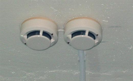
Fig. 2.Arrangement of detectors in pairs
More high level operability is achieved by using ring loops in address and address-analog systems with short circuit isolators. In this case, when a break occurs, the loopback loop is automatically converted into two radial ones, the breakage point is localized and all sensors remain in working condition, which keeps the system functioning in automatic mode. With a short circuit of the ring loop, only devices between two adjacent short circuit isolators are disconnected, and therefore most of the sensors and other devices also remain operational
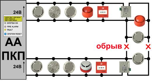
Fig. 3. Loopback
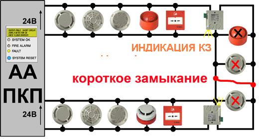
Fig. 4.Ring loop short circuit
A short-circuit isolator is usually two symmetrically-connected electronic keys, between which a fire detector is located. Structurally, the short-circuit isolator can be built into the base, which has two additional contacts (input and output plus), or can be integrated directly into the sensor, in manual and linear fire detectors and in functional modules. If necessary, a short-circuit insulator made in the form of a separate module can be used.
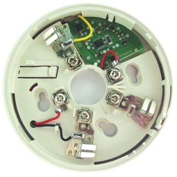
Fig. 5.Short circuit isolator in the sensor base
Obviously, systems with one “two-threshold” loop often used in Russia do not meet this requirement. In the event of a break in such a loop, a certain part of the protected area remains without control, and with a short circuit, control is completely absent. The “Fault” signal is generated, but until the fault is eliminated, the “Fire” signal is not generated by any sensor, which makes it impossible to turn on the fire extinguishing manually.
False Protection
Electromagnetic fields from radio transmitting devices can cause false signals in fire alarm systems and lead to activation of processes of electric initiation of gas release from fire extinguishing systems. Almost all buildings use equipment such as portable radios and cell phones; base transceiver stations can be located near or on the building itself at the same time by several cellular operators. In such cases, measures should be taken to eliminate the risk of accidental gas emissions due to exposure to electromagnetic radiation. Similar problems can arise if the system is installed in places of high field intensity - for example, near airports or radio transmitting stations.
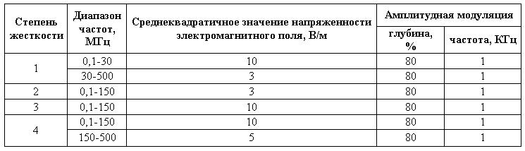
It should be noted that a significant increase in the level of electromagnetic interference in recent years caused by the use of mobile communications has led to an increase in European requirements for fire detectors in this part. According to European standards, the fire detector must withstand the effects of electromagnetic interference with a voltage of 10 V / m in the ranges 0.03-1000 MHz and 1-2 GHz, and a voltage of 30 V / m in the cellular ranges 415-466 MHz and 890-960 MHz, with sinusoidal and pulse modulation (table. 1).
Table 1. LPCB and VdS requirements for immunity of sensors to electromagnetic interference
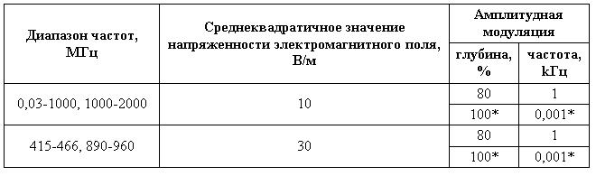
*) Pulse modulation: frequency 1 Hz, duty cycle 2 (0.5 s - on, 0.5 s - pause).
European requirements meet current operating conditions and several times exceed the requirements even for the highest (4th degree) stiffness according to NPB 57-97 "Devices and equipment for automatic fire extinguishing systems and fire alarms. Noise immunity and interference emission. General technical requirements. Test methods "(Table 2). In addition, according to NPB 57-97, tests are carried out at maximum frequencies up to 500 MHz, that is, 4 times less than European tests, although the" effectiveness "of interference with a fire detector is an increase in frequency usually increases.
Moreover, according to the requirements of NPB 88-2001 * p. 12.11, to control automatic fire extinguishing installations, fire detectors must be resistant to electromagnetic fields with a degree of rigidity of not less than the second only.
Table 2.Requirements for the immunity of detectors to electromagnetic interference according to safety standards 57-97
Frequency ranges and electromagnetic field strengths during tests according to NPB 57-97 do not take into account the presence of several cellular communication systems with a huge number of base stations and mobile phones, nor the increase in the power and number of radio and television stations, or other similar interference. Transceiving antennas of base stations, which are located on various buildings (Fig. 6), became an integral part of the city landscape. In areas where there are no buildings of the required height, antennas are installed on different masts. Usually, a large number of antennas of several mobile operators are located at one object, which increases the level of electromagnetic interference several times.
In addition, according to the European standard EN 54-7 on smoke detectors, for these devices the tests are mandatory:
- for moisture - first at a constant temperature of +40 ° C and relative humidity of 93% for 4 days, then with a cyclical change in temperature for 12 hours at +25 ° C and for 12 hours at +55 ° C, and with relative humidity not less than 93% for another 4 days;
- corrosion tests in an SO 2 gas atmosphere for 21 days, etc.
It becomes clear why, according to European requirements, the signal from two PIs is used only to turn on fire extinguishing in automatic mode, and even then not always, as will be indicated below.
If the detector loops cover several protected areas, the signal for initiating the release of the extinguishing agent into the protected area where a fire was detected should not lead to the release of the extinguishing agent into another protected area, the detection system of which uses the same loop.
Activation of manual fire detectors should also not in any way affect the start of gas.
Fire fact finding
The fire alarm system must comply with the recommendations given in BS 5839-1: 2002 for the corresponding system category, unless other standards are more applicable, for example, BS 6266 for the protection of electronic equipment. The detectors used to control the start of gas by an automatic fire extinguishing system must operate in matching mode (see above).
However, if the danger is of such a nature that a slow reaction of the system associated with the coincidence mode can be fraught with serious consequences, then in this case the gas is started automatically when the first detector is activated. Provided that the probability of false triggering of the detector and alarm is low, or people cannot be present in the protected area (for example, spaces behind suspended ceilings or under raised floors, control cabinets).
In general, measures should be taken to avoid unforeseen gas emissions due to false alarms. The coincidence of the operation of two automatic detectors is a method of minimizing the probability of a false start, which is essential in the event of the possibility of a false alarm of one detector.
Conventional fire alarm systems that cannot be individually identified by each detector must have at least two independent loops in each protected area. In address systems using the matching mode, the use of one loop is possible (provided that the signal for each detector can be identified independently).
Note: In zones protected by traditional addressless systems, after the first detector is activated, up to 50% of the detectors (all other detectors of this loop) are excluded from the match mode, that is, the second detector, activated in the same loop, is not perceived by the system and cannot confirm the presence of fire. Addressable systems provide control of the situation by the signal coming from each detector and after activating the first fire detector, which ensures maximum system efficiency by using all other detectors in coincidence mode to confirm the fire.
For matching mode, signals from two independent detectors should be used; different signals from the same detector cannot be used, for example, generated by a single aspiration smoke detector at high and low thresholds of sensitivity.
Type of detector used
Detectors must be selected in accordance with BS 5839-1. In some circumstances, earlier fire detection may require two different detection principles - for example, optical smoke detectors and ionization smoke detectors. In this case, a uniform distribution of each type of detector over the entire protected area should be ensured. Where a matching mode is used, it should usually be possible to match signals from two detectors operating on the same principle. For example, in some cases, two independent loops are used to achieve a match; the number of detectors included in each loop acting according to different principles should be approximately the same. For example: where four detectors are required to protect the room, and they are represented by two optical smoke detectors and two ionization smoke detectors, each loop should have one optical detector and one ionization detector.
However, it is not always necessary to use different physical principles of fire recognition. For example, taking into account the type of expected fire and the required speed of fire detection, the use of the same type of detectors is permissible.
Detectors should be placed in accordance with the recommendations of BS 5839-1, according to the required system category. However, when using the match mode, the minimum density of the detectors should be 2 times higher than recommended in this standard. To protect electronic equipment, the fire detection level must comply with BS 6266.
It is necessary to have means for quickly identifying the location of hidden detectors (behind suspended ceilings, etc.) in the "Fire" mode - for example, through the use of remote indicators.
Management and indication
Mode switch
The mode switching device - automatic / manual and only manual - should provide a change in the mode of operation of the fire extinguishing system, that is, when personnel access the unattended area. The switch must be brought into manual control mode and equipped with a key that can be removed in any position and should be located near the main entrance to the protected area.
Note 1: The key is intended for the responsible person only.
The key application mode must comply with BS 5306-4 and BS ISO 14520-1, respectively.
Note 2: Door lock switches operating with a locked door may be preferable for this purpose - in those cases, in particular, when it is necessary to ensure that the system is in manual control mode when personnel are present in the protected area.
Manual starter
The operation of the manual fire extinguishing device must initiate a gas release and requires two separate actions to prevent accidental operation. The manual starter should be predominantly yellow in color and have a designation indicating its function. Typically, the manual start button is closed by a lid and two steps are required to activate the system: open the lid and press the button (Fig. 8).

Fig. 8.The manual start button on the control panel is located under the yellow cover
Devices for which access is required to break the glass cover is undesirable due to the potential danger to the operator. Manual starters should be easily accessible and safe for personnel, and their malicious use should be avoided. In addition, they must be visually different from manual fire detectors of a fire alarm system.
Start delay time
A start delay device can be integrated into the system to allow personnel to evacuate employees from the protected area before the gas release begins. Since the time delay period depends on the potential speed of the spread of fire and the means of evacuation from the protected area, this time should be as short as possible and not exceed 30 seconds, unless a longer time is provided by the relevant department. The activation of the time delay device should be indicated by a warning sound signal audible in a protected area (“pre-start warning signal”).
Note: A long start-up delay contributes to the further spread of the fire and the risk of thermal decomposition products from certain extinguishing gases.
If there is a delay start device, the system can also be equipped with an emergency blocking device, which must be located near the exit from the protected area. While the button is pressed on the device, the countdown of the pre-start time should stop. When you stop pressing, the system continues to be in an alarm state, and the timer must be restarted first.
Emergency Lock and Reset Devices
Emergency blocking devices must be present in the system if it works in automatic mode, when people are present in the protected area, unless the contrary is agreed upon in consultation with interested parties. The appearance of the "pre-warning warning sound signal" must be changed to control the inclusion of the emergency blocking device, and there must also be a visual indication of the inclusion of this mode on the control unit.
In some conditions, fire extinguishing mode reset devices may also be installed. In fig. 9 shows an example of the structure of a fire extinguishing system.

Fig. 9. Fire extinguishing system structure
Sound and light indication
A visual indication of the status of the system should be provided outside the protected area and located at all entrances to the room so that the state of the fire extinguishing system is clear to personnel entering the protected area:
* red indicator - “gas start”;
* yellow indicator - “automatic / manual mode”;
* yellow indicator - “manual mode only”.
A clear visual indication of the operation of the fire alarm system within the protected area when the first detector is activated should also be provided: in addition to the sound notification recommended in BS 5839-1, the light sirens should blink so that people in the building are notified about the possibility of gas starting. The light alert must comply with the requirements of BS 5839-1.
Easily audible alert tones should be emitted at the following stages:
- during the delayed start of gas;
- at the start of gas start.
These signals may be identical or two distinct signals may be output. The signal turned on in stage "a" must be turned off when the emergency blocking device is operating. However, if necessary, it can be replaced during its broadcast by a signal that easily differs from all other signals. The signal turned on in stage "b" must continue to operate until it is turned off manually.
Power supply, eyeliner
The power supply for the fire extinguishing system must comply with the recommendations given in BS 5839-1: 2002, Clause 25. The exception is that the words “FIRE FIGHTING SYSTEM” should be used instead of the words “FIRE ALARM” on the labels described in BS 5839-1 : 2002, 25.2f.
The power supply to the fire extinguishing system must be connected in accordance with the recommendations given in BS 5839-1: 2002, clause 26 for cables with standard refractory properties.
Note: There is no need to separate the cables of the fire extinguishing system from the cables of the fire alarm system.
Acceptance and commissioning
After the installation of the fire extinguishing system has been completed, clear instructions should be prepared describing the procedure for its use and intended for the person responsible for the use of the protected premises.
All responsibility for the use of the system should be distributed in accordance with BS 5839-1, with management and personnel familiarized with the rules for safe handling of the system.
The user must be provided with an event log, a certificate of installation and commissioning of the system, as well as all tests for the operation of the fire extinguishing system.
The user must be provided with documentation relating to various parts of the equipment (junction boxes, pipelines), and wiring diagrams - that is, all documents relating to the composition of the system according to the items recommended in BS 5306-4, BS 14520-1, BS 5839- 1 and BS 6266.
These diagrams and drawings must be prepared in accordance with BS 1635 and, as the system changes, be updated to contain any modifications or additions made to it.
In conclusion, it can be noted that the British standard BS 7273-1: 2006 does not even mention duplication of fire detectors to increase the reliability of the system. Strict European certification requirements, the work of insurance companies, the high technological level of production of fire sensors, etc. - all this provides such high reliability that the use of backup fire detectors loses its meaning.
Materials used in the preparation of the article:
- Gas extinguishing. Status and prospects, tech. deer ZAO “Artsok” Merkulov V.A.
- Magazine “Security Systems” No. 5, 2007
In modern conditions of widespread electrification, not every fire can be extinguished with ordinary water. Some materials do not tolerate contact with liquids, so quenching with water causes them no less significant harm than fire.
Gas extinguishing systems are used in offices with expensive electrical equipment, museums, libraries, as well as on ships and aircraft.
Historical reference
For the first time, gas began to be used as a fire extinguishing agent in the second half of the 19th century. The first gas used for these purposes was Today it is used in gas fire extinguishing systems only in archives and cash vaults. Freons became more widespread. For the first time in Russia, gas fire extinguishing was carried out in the 30s of the XX century.
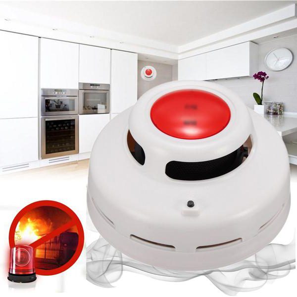
Briefly about the equipment and its scope
Gas fire extinguishing is one of the many ways to combat fire, in which the following compressed gases (for example, nitrogen and argon) and freons are used.
An automatic installation consists of the following elements: a container with gas, a pipeline with nozzles, a control panel, central unit management, announcers.
A key element of the system is a gas fire extinguishing module, structurally consisting of a container with gas and a starting device. As a rule, a gas cylinder can be refilled repeatedly after use. If the system is complex and consists of more than one module, they are combined with special devices - collectors.
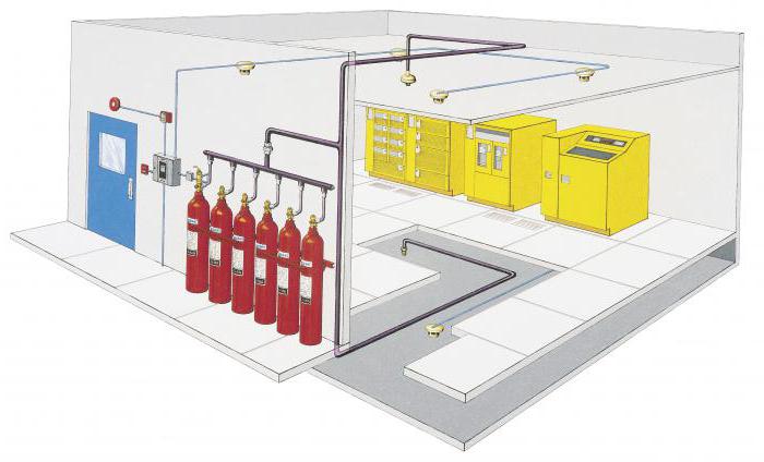
The principle of the gas fire extinguishing system
Gas fire extinguishing is carried out according to the following principle: non-combustible gases are supplied to the ignition zone under the influence of high pressure, displacing oxygen from the air. As is known from the school chemistry course, in the absence of oxygen in the air, the combustion process slows down and ignition stops.
The rooms equipped with gas fire extinguishing systems are also equipped with special sensors that transmit information on the fire that has begun to the control panel. After the received signal, it starts the fire extinguishing scenario: ventilation is blocked in the room, non-combustible gas is supplied through the pipe through the sprayers. The higher its concentration, the faster the fire will be put out. As a rule, gas fire extinguishing lasts less than one minute.
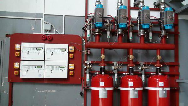
Automatic installations of gas fire extinguishing systems, their types
Automatic UGPs are typically used in non-residential premises, where it is difficult to notice a fire without an automation system, as well as in warehouses with explosive and combustible substances. The main criterion for the classification of automatic fire extinguishing systems is mobility. On this basis, they are divided into mobile, portable and stationary.
In the first case, the equipment will be installed on the chassis or tracks; it can be both self-propelled and towed.
Fixed installations are located directly in the customer’s premises and are controlled by remote control.
Wearable are more common than others. These are fire extinguishers, the presence of which is mandatory for each room.
Mobility is not the only criterion for automatic installations. They are also classified by the method of control and supply of non-combustible substances, as well as by the total amount of extinguishing.
There are a great many ways to control a fire extinguishing installation, and besides, they can be combined with each other. That is, each manufacturer decides for himself how this or that model will be controlled
Non-combustible mixture can be supplied in two ways: modularly, using removable cylinders or centrally, from a common tank.
In terms of extinguishing, automatic gas extinguishing installations are local or complete extinguishing. In the first case, the substance is supplied only to the source of ignition (for example, gas fire extinguishing by the server can be organized only in this way), in the second - along the entire perimeter of the room.

Design, calculation and installation of gas fire extinguishing systems
Installation of a gas fire extinguishing system requires careful observance of all applicable laws and full compliance with the requirements of each projected facility. Therefore, it is better to entrust such a complex and painstaking business to professionals.
When installing such a system, it is necessary to take into account many factors: the number and area of \u200b\u200ball rooms, room features (such as a suspended ceiling or false walls), general purpose, humidity characteristics, as well as ways to evacuate citizens in case of emergency.
In addition, there are some nuances in this matter. For example, when installing equipment in a room with high traffic, installation should be performed in such a way that, when the fire extinguishing system is activated, the oxygen concentration in the air remains within the limits allowed by the norms.
It is also necessary to remember that each gas fire extinguishing module must be protected from external factors.

Routine maintenance of gas fire extinguishing systems
In order for gas fire extinguishing installations to function properly during the entire period of operation, they need preventive maintenance from time to time. Every month, all components of the system should be checked for their tightness, and ignition sensors - for operability.
After each actuation of the fire extinguishing system, it is necessary to refuel the gas tanks and reconfigure
All the listed preventive works are carried out directly at the customer’s site, that is, they do not require constant reinstallation of the system.
In addition, routine maintenance of the gas extinguishing system includes regular technical inspection of the modules. Each gas fire extinguishing module must be checked once every 10-12 years.
What is included in the installation work?
Before installing gas equipment, it is necessary to make sure that the manufacturer has state-certified certificates. It will not be superfluous to verify the license of the contracting company that carries out its installation.
Then, you definitely need to make sure that the ventilation systems are working, and only then start working.
All modules of the device are combined into a single system responsible for the operation of the device in case of fire, and control the situation in the room. At this stage, the owner must make sure that the design proposed by the master not only suits him aesthetically, but also does not interfere with the work of the staff.
After the installation of the system, the contractor prepares the test reports and technical documentation for each of its elements.
Automatic gas fire extinguishing installations are an effective element of comprehensive fire protection of premises for various purposes. Such installations operate in conjunction with, which detects signs of fire and activates the device.
The effectiveness of the modules depends on the correct selection of a gas extinguishing agent (GOTV), depending on the characteristics of the protected premises. If the GOTV selection, design and installation of the installation were carried out professionally, the system eliminates the fire or localizes the fire before arrival fire brigade, which will significantly reduce possible damage.
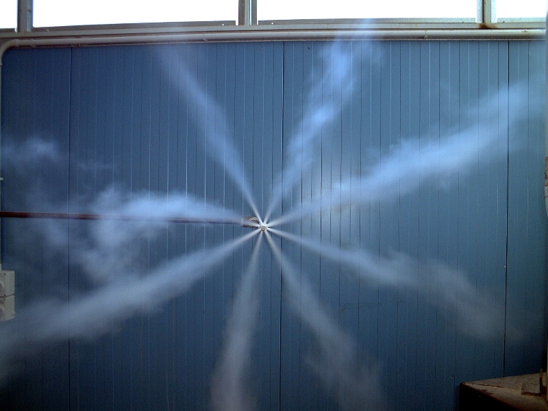
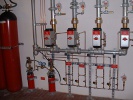
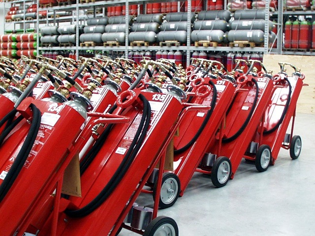
Gas extinguishing module
IHL or gas fire extinguishing modules are used to extinguish solids (except light and alkali metals), as well as liquids and ignited gases (fires, classes A, B and C). They can also extinguish electrical wiring or non-de-energized electrical equipment. Special fire extinguishing gas (GOTV) is able to be stored in the IHL under pressure for a long time.
In the event of a fire in a controlled room, a fire extinguishing gas is released, after which it fills the entire space where there is a quick elimination of all burning foci.
The extinguishing mechanism depends on the type of GOTV. Usually this is a decrease in oxygen concentration, inhibition of the chemical reaction of combustion, cooling of the combustion zone, or a combination of several mechanisms. The method of extinguishing is voluminous, therefore, gas is efficient in confined spaces (the premises should not have constantly open apertures), while gas will not damage property and will not cause material damage.
Installation of a gas fire extinguishing system begins with the calculation of the parameters of the protected premises (volume and area of \u200b\u200bthe room, the presence of ventilation, employees and the fire hazard class).
The Flame E1 company has been specializing in the implementation and installation of such modern fire safety systems for several years. In our assortment you will find installations and containers for gas storage, designed for rooms of any volume.
Experienced employees of Flame E1 will analyze the premises, types of materials and stored property, after which they will recommend the type of gas and installation design. We have equipped gas fire extinguishing systems with more than one large facility in Russia, and many state and commercial organizations are our regular customers.
Gas extinguishing has more than a century of history. The use of carbon dioxide (CO 2) for extinguishing fires first began at the end of the 19th century in Western Europe and the United States, but this method of extinguishing fires became widespread only after the Second World War, when refrigerants began to be used as the main component of GOS.
Basics and classification
Currently, regulatory documents in force in the Russian Federation allow the use of gas extinguishing agents based on carbon dioxide, nitrogen, argon inergen, sulfur hexafluoride, and also HFC 227, HFC23, HFC 125 and HFC 218. According to the principle of operation, all GOS can be divided into two groups:
- Deoxidants (oxygen displacers) - substances that create a concentrated cloud around the burning area, which prevents the flow of oxygen and thus "suffocates" the source of ignition. GOS based on carbon dioxide, nitrogen, argon and inergen belong to this group.
- Inhibitors (combustion suppressors) - substances that enter into chemical reactions with burning substances, which take energy from the combustion process.
According to the storage method, fire extinguishing gas mixtures are divided into compressed and liquefied.
The scope of gas fire extinguishing installations covers industries in which extinguishing with water or foam is undesirable, but contact of equipment or stored stocks with chemically aggressive powder mixtures is also undesirable - hardware rooms, server rooms, computer centers, ships and aircraft, archives, libraries, museums, picture galleries.
Most of the substances used for the production of GOS are non-toxic, but the use of gas fire extinguishing systems creates an environment unsuitable for life in a closed room (this is especially true for GOS from the group of deoxidants). Therefore, gas extinguishing systems pose a serious danger to human life. So on November 8, 2008 during sea trials of the Nerpa nuclear submarine, the unauthorized operation of a gas fire extinguishing system resulted in the death of more than twenty crew members of the submarine.
In accordance with regulatory enactments, all automatic fire extinguishing systems with GOS as a working substance must, without fail, allow the possibility of delaying the supply of the mixture until the personnel is completely evacuated. Premises in which automatic gas fire extinguishing is used are equipped with “GAZ! DO NOT ENTER! ” and "GAS! GO away! ” at the entrance to and exit from the premises, respectively.
Advantages and disadvantages of gas fire fighting
Fire extinguishing with the help of GOS has become widespread due to a number of advantages, including:
- fire extinguishing with the help of GOS is carried out throughout the volume of the room;
- extinguishing gas mixtures are non-toxic, chemically inert, when heated and in contact with burning surfaces do not decompose into toxic and aggressive fractions;
- gas fire extinguishing practically does not harm equipment and material values;
- after extinguishing, the emergency conditions are easily removed from the premises by simple ventilation;
- gOS application has a high fire extinguishing rate.
However, gas fire extinguishing also has some disadvantages:
- gas fire extinguishing requires room sealing
- gas fire extinguishing is ineffective in large premises or in open space.
- storage of equipped gas modules and maintenance of the fire extinguishing system is fraught with difficulties associated with the storage of substances under pressure
- gas extinguishing systems are temperature sensitive
- GOS are unsuitable for extinguishing a fire of metals, as well as substances that can burn without oxygen.
Fire extinguishing installations using GOS
The gas fire extinguishing installations by the degree of mobility can be divided into three groups:
- Mobile gas fire extinguishing installations - fire extinguishing installations mounted on a wheeled or tracked chassis, towed or self-propelled (Sturm gas fire extinguishing installation).
- Portable primary extinguishing media - fire extinguishers and fire extinguishing batteries.
- Stationary installations - permanently mounted fire extinguishing installations using GOS, automatic and triggered by command from the remote control.
In non-residential premises, in warehouses and storages, at enterprises associated with the production and storage of combustible and explosive substances, automatic gas fire extinguishing systems are widely used.
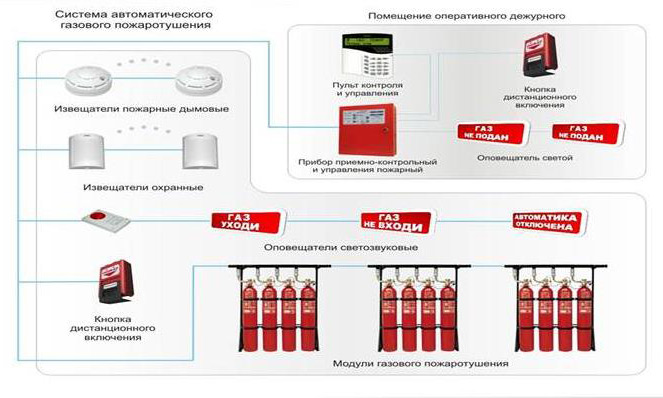
Since gas fire extinguishing is highly dangerous for the enterprise personnel, in the case of installing an automatic fire extinguishing system using GOS in enterprises with a large number of employees, integration of the system automation with an access control and management system (ACS) is required. Moreover automatic system fire extinguishing should, at the signal of the fire detectors, maximize the sealing of the room in which the fire is extinguished - turn off the ventilation, and also close the automatic doors and lower the protective shutters, if any.
Automatic gas fire extinguishing systems are classified:
- By extinguishing volume - extinguishing the full volume (gas fills the entire volume of the room) and local (gas is supplied directly to the source of ignition).
- According to the centralization of the supply of the extinguishing mixture, they are centralized (gas is supplied from the central reservoir) and modular.
- By the method of initiating the extinguishing process - with electric, mechanical, pneumatic, hydraulic descent or a combination thereof.
Equipping the facility with a gas fire extinguishing system
The initial calculation and planning of the installation of a gas fire extinguishing system begins with the selection of system parameters, depending on the specifics of a particular object. Of great importance is the correct choice of extinguishing agent.
Carbon dioxide (carbon dioxide) is one of the most inexpensive options for GOS fire fighting. Refers to fire extinguishing substances-dioxidants, in addition, it has a cooling effect. It is stored in a liquefied state, it requires weight control of substance leakage. Carbon dioxide-based mixtures are universal, the restriction to use is fires with the ignition of alkali metals.
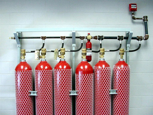
Freon 23 is also stored in liquid form. Due to its high inherent pressure it does not require the use of displacing gases. It is allowed to be used for extinguishing rooms in which people can stay. It is ecologically safe.
Nitrogen is an inert gas, also used for fire extinguishing systems. It has a low cost, but due to storage in a compressed form, nitrogen-loaded modules are explosive. If the nitrogen gas fire extinguishing module does not work, it must be abundantly irrigated with water from the shelter.
The fire extinguishing steam installations are of limited use. They are used at facilities that generate steam for their work, for example, at power plants, ships with steam turbine engines, etc.
In addition, before designing, it is necessary to choose the type of gas fire extinguishing installation - centralized or modular. The choice depends on the size of the object, its architecture, number of storeys and quantity separate premises. Installation of a centralized type fire extinguishing installation is advisable to protect three or more rooms within the same facility, the distance between which does not exceed 100m.
At the same time, it should be taken into account that centralized systems are subject to a large number of requirements of the normative NPB 88-2001 - the main normative documentgoverning the design, calculation and installation of fire fighting installations. Fire extinguishing gas modules, according to their design, are divided into unitary modules - they include one tank with a compressed or liquefied gas extinguishing mixture and a gas displacer in their design; and batteries - several cylinders connected by a collector. Based on the plan, a gas fire extinguishing project is being developed.
Designing a fire system using GOS
It is desirable that the whole range of work related to equipping the facility fire system (design, calculation, installation, commissioning, maintenance) was carried out by one executing company. Design and calculation of a gas fire extinguishing system is carried out by a representative of the installation company in accordance with NPB 88-2001 and GOST R 50968. Calculation of installation parameters (quantity and type of extinguishing agent, centralization, number of modules, etc.) is based on the following parameters:
- number of rooms, their volume, the presence of false ceilings, false walls.
- area of \u200b\u200bconstantly open openings.
- temperature, barometric and hygrometric (air humidity) conditions at the facility.
- the presence and mode of operation of personnel (ways and time of personnel evacuation in case of fire).
When calculating the estimates for the installation of fire extinguishing system equipment, some specific aspects should be taken into account. For example, the cost of one kilogram of a fire extinguishing gas mixture is greater when using modules with compressed gas, since each such module contains a lower mass of substance than a module with liquefied gas, therefore, the latter will need less.
The cost of installation and maintenance of a centralized fire extinguishing system is usually less, however, if the facility has several sufficiently remote rooms, the savings are “eaten up” by the cost of pipelines.
Installation and maintenance of gas extinguishing stations
Before starting installation work on the assembly of a gas fire extinguishing installation, it is necessary to make sure that there are certificates for the equipment subject to mandatory certification and check the installation company for a license to work with gas, pneumatic and hydraulic equipment.
A room equipped with a gas fire extinguishing station is necessarily equipped with exhaust ventilation to remove air. The rate of air removal is three for chladones and six for deoxidants.
The manufacturer carries out the installation of fire extinguishing modules or centralized balloon tanks, trunk and distribution pipelines and starting systems. The modular or centralized pipeline part of the gas extinguishing station is integrated into a single automated control and monitoring system.
Pipelines and elements of an automated control system must not interfere with the appearance and functionality of the premises. Upon completion of installation and commissioning, an act of completion is executed, and an act of acceptance and transfer to which are attached test reports and technical data sheets of the equipment used. A maintenance contract is concluded.
Performance tests of equipment are repeated at less than once every five years. Maintenance gas extinguishing systems includes:
- regular tests of the performance of gas extinguishing station elements;
- routine maintenance and equipment repair;
- weight tests of modules for the absence of leakage of GOS.
Despite certain difficulties associated with installation and use, gas fire extinguishing systems have a number of undoubted advantages and high efficiency in their field of application.