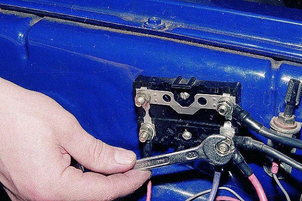
How to connect automatic locks on a car. Universal central locking remote control unit
central locking
To search for circuits, try to use a voltmeter (especially in cars of the last years of production), since using a lamp probe can damage the car's electricians !!!Usually, connection to the central lock is the most difficult and long task when installing an alarm. To connect to the central lock you need to know which type of central lock is on your car. These types are not so many.
1st type: central locking negative momentum controlled. Simply put, there are two wires, when applying a minus to which the doors are locked or unlocked. We sit on the probe on the ground and poke into the wires leaving the door (the probe should not be a diode, but with a light bulb, otherwise the minus may not be enough to control central lock). When hit on the desired wire, the doors will close or open. Here they are - the wires we need! Be sure to check that these two wires work even with the driver's door closed. If you can’t find the wires from the door, but you are sure that in your car it’s the central lock controlled by minus, then you need to look for wires in other places.
Consider a circuit for connecting an alarm to a central lock. Where, for example, is there a central locking unit in your car? Open - close the doors with the remote control or using the central lock control button and listen to where the relay clicks. These relays are located in the central locking unit. See what this block is? If it is not difficult to disassemble - disassemble. See - there is a relyushka (s) there (yat). Try to apply minuses to the relay feet with a probe. In most cases, if you manage to disassemble the central locking unit, there are two points, when applying a minus to which, the doors are controlled. Here it will be necessary to solder wires from the alarm.
Another place to find the wires that control the central lock is the driver’s door (in many Honda, by the way, the central locking unit is located in the driver’s door). Try through the probe to apply the minuses to the wires in the door, without disconnecting the power window control unit and the central lock control button. Maybe the right wires are here. Pull the wires from the alarm at the door.
As you already understood, in this we need that from the signaling to the wires controlling the central lock, the minuses would come. If you have a car alarm with low-current negative outputs for controlling the central lock, then connect these wires directly to those that you found using the probe. If you have a car alarm with low-current negative / positive outputs (this is when the minus signal on one wire when arming, for example, is armed, and the plus signal on the second one), then connect as described above, but through the diodes the minus goes on the wires of the central lock, plus - does not go. This is important - otherwise you can burn the alarm or, even worse, some equipment in the car. If you have an alarm system with power outputs to the central lock (with built-in relays), then connect as follows: normally-open (NO) contacts of the built-in relays to minus, normally-closed (NC) contacts are not used, common (O) contacts to the wires found management.
2nd type: central lockingdriven by positive momentum. Again, as in the 1st type, there are two control wires, when supplying them with a plus, the doors will be unlocked or locked. The search methodology is absolutely identical to the above (with a negative control impulse), only the probe does not sit on the minus, but on the plus. In this connection to the central lock, we need the pluses to come from the alarm to the wires that control the central lock. If you have an alarm with low-current negative outputs for controlling the central lock, then you need to use additional relays and connect as follows: common relay contacts to the wires found, NC contacts are not used, NO contacts and one side of the relay coils are positive, the second side of the coils to wires from car alarms. If you have an alarm with low-current negative / positive outputs, then connect directly to the wires found through the diodes - the pluses go to the wires of the central lock, the minuses - no. This is important - otherwise you can burn off the car alarm or, even worse, some equipment in the car. If you have an alarm system with power outputs to the central lock (with built-in relays), then connect as follows: NO contacts of the built-in relays for plus, NO contacts are not used, O-contacts are found to the control wires.
3rd type: central locking reverse polarity. This type of harmful (often found in Americans). Here you have to connect directly to the power wires. We sit down on the plus probe and look for wires on which the minuses hang (the probe lamp is on), we control the central lock from the remote control or buttons. If the probe light goes out when closing or opening, and then lights up again, then the probe is transplanted to minus and poke into the same wire and again control the central lock. If the probe lamp lights up when closing or opening, then this is one of the wires we need. Similarly, we are looking for a second power wire. Roughly speaking, we found wires that directly control door drives. What is a drive? Yes, ordinary motors! Plus on one wire, minus on the other - the motor twisted in one direction, and the doors closed, reversed the polarity - the motor twisted in the other direction, and the doors opened.
When connecting an alarm to such a castle, you need to be especially careful. The fact is that here you have to break the found power wires and connect to the breaks with an alarm. And if you mess up the ends (for example, pick up a wire from the alarm to the end that goes to the button, but you need to end to the one that goes to the drive), you can burn something important and expensive (fuses will fly at best). Therefore - caution and measure seven times, check, think - then just do it!
So, we found the power wires (usually they come out of the driver’s door), now we pick up. First, cut the wires found. If you have an alarm with low-current negative / positive outputs, then you need to use 2 relays. We pick up as follows. NO contacts of the additional relays for plus, NC contacts of the additional relays to the wires going to the central lock control button or to the central locking unit, O-contacts of the additional relays to the wires going to the door drives. You hook the outputs from the alarm to the coil of additional relays (to either side), and put the second leg of the relay on the plus or minus (depending on the outputs of your car alarm: if negative - then plus, if positive - then minus). If you have an alarm with power outputs, then we connect as follows: НР-contacts to plus, NC-contacts to wires going to the central lock control button or to the central lock block, О-contacts to wires going to the door electric drives.
If, for example, you find where the central lock unit is located, but you cannot disassemble it, then find the power wires coming out of it to the door electric drives and pick them up as a central lock with variable polarity. This is especially simpler when the alarm has power outputs for controlling the central lock, and applying minuses / pluses to the control wires of the central lock unit does not give anything (such blocks are on Chevrolet Niva, some Honda, on domestic VAZs with a factory central lock, etc. d.).
By the way, if you need to install your own drives (you do not have a central lock in your car), then the connection is similar to this type, with the only difference being that the NC contacts of the relay (both built-in and remote) must be connected to the minuses. Well, of course, nothing needs to be cut - you throw your wires and cling to them (i.e., the relay O-contacts go to the drive).
One more type central castle4th: vacuum. It is found mainly in German car manufacturers. Here, the control goes along one wire, when unlocking on this wire is plus, when locking is minus. This wire is located either at the compressor (in the trunk or under the rear seat) or moves away from the central locking control button. We are looking for it: we sit down on the probe with a minus, poke in the wires and control the central lock. When opening, the probe lamp should light up. We are transplanted with a probe to the plus - on the same wire mass should appear when closing. We cut the wire found and pick it up in gaps, but carefully, as in the previous type, otherwise it is fraught with consequences for auto electronics or for signaling. To make sure that the wire is found, do the following: pass through the probe into the gap of the wire found to the side that goes to the compressor, plus, and then minus. Doors should open first, then close. If you have a car alarm with built-in power relays, then we do this: NO contact of the unlock relay to plus, NO contact of the relay to ground, NC contact of the unlock relay to open the wire to the control button of the central lock, NC contact of the relay to O - contact of the unlocking relay, O-contact of the locking relay in the gap on the compressor side. If the alarm is with low-current negative outputs, then connect as described above, using additional relays. From the alarm wires go to the relay coils, the other side of the coils sit on the plus. If the alarm is with low-current positive outputs, then the connection is similar to the previous one, only one of the sides of the coils is set not to plus, but to minus. Sometimes, when connected to this type of central lock, it was necessary to disassemble the air pump and cut the power wires to control the pump motor directly inside.
Of course, not all methods and tricks of connecting to car locks are described here. But with this knowledge, you can easily connect to most central locks.
The central lock is an electromechanical system for centralized locking of car door locks, which allows you to simultaneously close or open all doors of the car, by turning the key in the lock of one door or the remote control (key fob), which is mounted in the key or in a separate key fob. Together with the doors, the system closes and opens the trunk and the hatch of the fuel tank, if it is equipped with a drive (actuator). If there are electric windows in the car, the central lock may have a "comfort" system that automatically closes all the windows and the sunroof of the car.
Central locking is a complex system consisting of many components and to connect an alarm to it you need to have an idea. how it works and what it consists of.
Here we will look at how the central lock is arranged, what happens and how, depending on the type, to connect an alarm to it. Schemes of central locks and explanations will allow us to understand and shed light on the topic of connecting an alarm to the central lock of a car.
Central locking device
Central locking consists of:
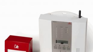
Central locking control unit
The central locking control unit is the electronic brain center of the entire system. The complexity of the blocks can be different, from very simple to microprocessor and very complex. As a rule, the entire electronic part is placed in one housing with connectors, but with the advent of the CAN bus in modern cars, the control part can be divided into separate blocks scattered in different parts of the car.
The control unit monitors the condition of the end door sensors (limit switches), contact groups of door locks, the position of the lock control buttons and other sensors. All sensors are connected to the unit by wires through which they inform the unit of their status and changes, and it responds to changes in incoming signals by controlling the wires of electric drives (actuators) that block or unlock the doors, trunk and hatch of the car's gas tank.
In some cases, the Central unit can still control the "turn signals" of the car, blinking them when closing and opening the doors. If this option is present, then you can connect an alarm to these wires to control the turning lights of the car.
The control unit can also have a built-in receiver for remote control of the central control unit. This receiver can be located either inside or separately from the control unit and is connected to the unit by wires that can be used to connect the alarm control with a central lock.
I want to note: What if you find the unit in the car and it can do a lot, then we connect 80% of the alarm wires to it and only the siren and the engine lock remain! Well, even alarm sensors.
Input Sensors and Buttons
input sensors in the system are:
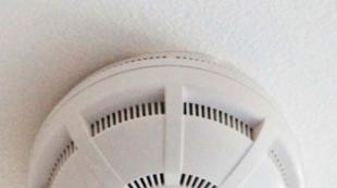
- door limit switches, they determine whether the door is closed and open in relation to the car body. The light in the cabin directly depends on the state of these limit switches and of course we connect them to the alarm to protect the doors.
- microswitches in the design of the lock, they determine where the key is turned in the door lock and, depending on this, tells the unit to lock or unlock the door. (Can be used to connect an alarm)
- microswitch in the electric drive of the lock - it determines the current position (locked or unlocked), is also used to control the central locking circuit.
- As a button, three-pin (with a common and two normally open contacts) two-way button is used, there are still two contact or five contact buttons for controlling the central lock. There can be one of these buttons in the car on the driver's door or on the panel, or two on the left and right front doors. By pressing the button in one or the other direction, we let the control unit know whether to lock or unlock the doors. The wires of these buttons can also be used to connect an alarm. It should be noted that there may not be buttons.
Actuators (actuators)
Actuators of central locks are mainly used electromechanical (hereinafter referred to as the Electric Drive), but in the case of a pneumatic system, actuators operate by air pressure (hereinafter).
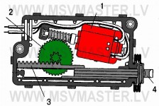
Electric drive
Electric door locks are available in several designs and differing in the value of traction (from 2, 5 to 6 kg).
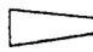
All electric drives have a plastic case with a built-in DC motor and a plastic (or metal) gearbox that converts rotational motion into translational motion. A change in the direction of translational motion of the output rod of the engine is made when the polarity of the supply voltage is changed, as a result of which the motor rotates in one direction or the other, which unlocks or locks the door lock. The most common are electric drives T-shaped ("pistol") and square types.
There are electric drives with two electric motors, one locks / unlocks the lock, and the other blocks the ability to mechanically open the lock by pulling the handle inside the car or raising the lock rod. These electric drives are controlled by three wires (Classic example BMW cars). In modern vehicle designs, electric drives are mounted in a common housing door lock together with the mechanical part.
Electric locks are controlled by a pulse voltage of 0.8 -1.5 s. This time is enough for the locks to open or close. It is impossible to supply power to electric motors exceeding this time, otherwise this will lead to their failure, in other words, they will burn out.
Electric motors are distinguished by the presence or absence of a contact microswitch in them, mechanically connected with a retractable rod. Three wires of this microswitch are brought out and together with two power wires of the engine itself and form the so-called five-wire Electric drive, which is usually installed in the front doors. The microswitch integrated in them, together with the control unit, provides the operation of two-wire electric drives of the rear doors when manually unlocking / locking the front door lock using a metal door key or a lock control button.
Examples of electric drives for closing / opening car doors.
700 423 351
386
351
386
 278
182
278
182
 645
432
645
432
Pneumatic drive
The pneumatic actuator consists of a plastic case with a fitting for supplying air and an outlet for the rod, inside a rubberized membrane with a rod attached to it.
The principle of operation is very simple. When air is supplied to the drive, the membrane is pushed up, and when air is sucked, it falls down by moving the rod, locking or unlocking the door lock.
Pneumatic actuators also differ from each other by the presence or absence of a contact microswitch in them, mechanically connected to a sliding rod. The principle of the microswitch is the same as that of.
Some pneumatic actuators use built-in solenoids (an electromagnet with a moving core). These actuators do not allow an attacker to open a lock, for example with a ruler. When an attempt is made to raise the rod without the knowledge of the control unit, the microswitch is activated and the unit gives voltage to the solenoid, while the core of the solenoid blocks the rod preventing the door from being opened by robbery, and the compressor additionally creates a vacuum, returning the rod to the closed state.
Currently, car manufacturers have abandoned the use of pneumatic systems of central locks and only electric drives are used!
To summarize the interim results: We now know how the central car lock works, we found out that it can be controlled in different ways: using the contacts of the central control button, the contact group of the door lock, the contact group of the actuator and, in some cases, the power control wires of the actuator. Further we will consider the types of central locks and how to connect them to the alarm so that it can control them. All wiring diagrams are presented for alarms that have built-in lock control relays: three wires for closing and three wires for opening.
Types of central locking control
- Central locking control via CAN adapter
- Installation of the central lock, if it is not on the car
Positive lock central control circuit
 410
336
410
336
On the pattern A Shown is a central car lock with an electronic unit and a positive control signal. This type of control is typical for General Motors Corp., Renault, Chrysler, BMW (E39, E34, E38), VW Passat and some Ford models.
To control such a lock, it is enough to apply a positive, short pulse of 1s to the control wires, Block C.Z. will react and, accordingly, will close or open the door locks. The control is low-current, if you connect the control with a “crocodile” to +12 volts, and use a sharp probe to pierce the wires in the bundle at the exit of the driver’s door, then, if you get on the right wire, the locks will work, so you can find the right control wires. The diagram shows an example of connecting an alarm to control the central lock with plus control, in principle, the alarm simulates pressing a button in one or the other direction, closing or opening the central lock.
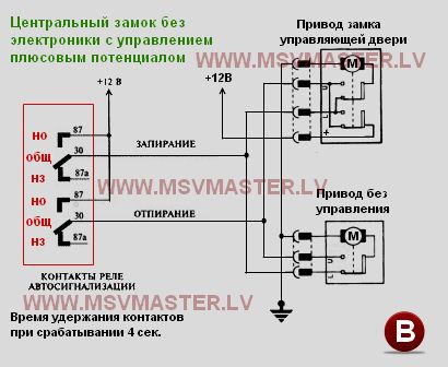
On the pattern B The central lock of a car is shown, which does not have an electronic part and is controlled by the positive potential of the drive itself with the help of a contact group inside it. There can be several control locks, for example, Two - driver and front passenger doors. Such central locking systems are used in some FORD vehicles after 92g.
The principle of work is brilliantly simple. The motors in the drive rotate in one direction and have 2 rest points, one is closed - the rod is pulled as much as possible inside the drive and the state is open - the rod is maximally extended from the drive.
Diagram Central locking without electronics with plus control
 410
336
410
336
The diagram shows the state of the locks in the open state. If you close the control door, for example using a key, the door will close mechanically and the contact group inside will switch, as a result of which a voltage of + 12V will appear on the contact ( L) (Lock-Close), all other drives are open and the motors are connected to this wire through their own contacts. As a result, the engines turn on and retract their rods, closing the locks.
When the rods retract, the internal switches will trip and disconnect the motor from the contact ( L) and connect it to the contact ( U) (Unlock-Open). As a result, all the locks are closed and the system is in balance. Now if you apply a positive voltage to the contact ( U), the motors will set in motion and open the locks, the motors will switch to contact ( L) and the system will again be in balance.
On the pattern B shown. how to connect the contacts of the alarm relay. so that she runs such a central castle. You need to set the time for 4 seconds, so that the drives have time to close / open. Power supply to the alarm relay must be connected via a fuse.
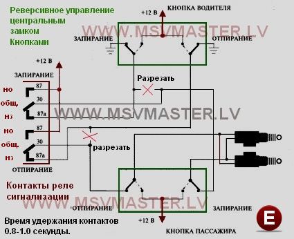
A: Reverse lock control with power buttons
 425
346
425
346
On the pattern E The central locking of a car with reverse control from power buttons installed in the casing of the driver and passenger doors is shown and does not have an electronic control unit. This drive control method is used on some cars of the 90s, mainly American ones: Chrysler, Ford, Chevy Cavalier, etc.
If you look at the lock control button installed in the driver’s door, then five wires will depart from it: one wire with constant power supply +12 V, two wires with constant weight and two wires with ground in the initial state. When you press the button in one or the other direction, the negative potential will change to positive on one or the other wire. when locking on the locking wire, when unlocking on the unlocking wire. In this case, the electric drives will close or open the car door locks.
The diagram shows how you need to connect the alarm wires to control such a lock. In fact, connecting the contacts of the alarm relay copies the button in the passenger door. During installation, you must be especially careful, because improper connections will lead to instant damage to system elements. As protection, it is necessary to use a 10-15 A fuse in the +12 V power supply circuit.
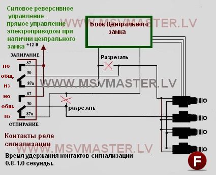
B: Reversible control with central locking unit
 425
346
425
346
On the pattern F shows a method of connecting an alarm for direct control of electric drives in the presence of a control unit Ts.Z ..
This control is suitable for almost any type of central lock except vacuum and provided that when the mechanical action on the lock rod, the handle or the latch on the door, all locks are closed and open. Only in this case will there be a guaranteed closing of all doors, and not just one.
It is ideal to connect if the control unit is a separate unit and the outputs to the electric drives are common. In this case, we find the control unit, determine the power wires and, as in the diagram, cut them and connect the wires from the alarm to the gap.
It is important not to confuse with the connection, otherwise you can disable the relay and the alarm track or central locking unit. Remember the main rule of reverse control - General contacts of the control relay from the alarm, always connected to the drive side.
If the control of the lock is mounted in the General unit, then here the frequent power wires for controlling the drives go out of different connectors, which complicates the task somewhat. In this case, we can apply this connection to one of the electric drives of the car’s control doors. For example: We find power wires going to the driver’s door. This can be done with the help of car controls:
- We hang the crocodile on the mass, pierce the wire with a probe and close / open the lock using the native remote control or the car’s lock control button. On the wires we need, the control light will flash.
- Thus, we find the two wires we need and to make sure that these are the wires, we put the control on both wires, on one crocodile. to another probe, for what what, no difference. When opening and closing the door lock, the control lamp should flash at the beat of the actuator.
- We cut the closing wire, now when the central lock is triggered, the drive should be silent and not show signs of life, both for opening and closing.
- For a short time, it is possible to apply +12 volts to the cut-off wire leading to the door through a 5A fuse. The door electric drive should close and the entire central lock will work.
- If this happens, then cut the second wire, and the first temporarily connect. We briefly apply +12 V to the side of the door (drive) and the drive should work and open its door first, and then all the other locks should open.
- If all is well, then in the breaks of both wires we connect the wires from the alarm according to the scheme presented here. It is important not to make a mistake and carefully check the correctness of your connection.
Attention: When searching and checking the wires, the lock dog must be latched and the door button must be turned off or pressed so that everything is emitted correctly - the doors are tightly closed, there is no key in the ignition switch.
C: Reversible drive control
 425
346
425
346
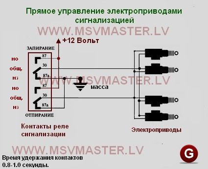
On the pattern G it is shown how to switch the contacts of the alarm relay for direct control of the electric drives of the lock through two wires by reversing the potentials on them.
In the initial state on both wires there is a negative potential of -12 Volts, it gets there through the normally closed contacts of the closing relay and the unlocking relay.
Upon receipt of a signal from the remote control to arming, the locking relay operates and disconnects the common contact from the minus and connects it for 1 second to a normally open contact on which there is a positive potential of +12 Volts, and then the common contact returns to its original state. This time is enough for the engine to rotate in one direction to remove the actuator stem inside the housing and the locks to close.
When a signal from the remote control is received for disarming, the unlock relay activates and disconnects the common contact from the minus and connects it for 1 second to a normally open contact on which there is a positive potential of +12 Volts, and then the common contact returns to its original state. This time is enough for the engine to rotate in the opposite direction to extend the actuator stem from the housing and the locks open.
Such a connection scheme is applicable in the case when the car does not have, not C.Z., not electric drives. Self-installed electric drives in the doors are connected according to this scheme.
In the event of a breakdown of the Control Unit, you can disconnect all drives from it and, according to this scheme, connect them to the alarm.
Central locking control with pneumatic electric compressor
This type of central lock uses an air compressor to control the locks and is used in Mercedes Benz, Audi, Volkswagen cars.
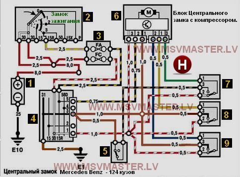
The central lock of the car Mercedes Benz - 124 body.
Consider connecting an alarm to a pneumatic lock, using the example of a car Mercedes Benz - 124 Body - Circuit-H. This car has a classic compressor and pneumatic actuators. In the driver and front passenger and doors, as well as in the trunk lid, pneumatic actuators with three contact switches are installed.
 410
336
410
336
- Battery
- Contact group ignition
- Fuse box
- Connection block
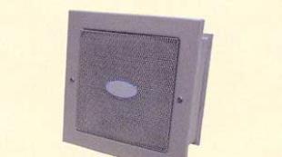
- Warning buzzer switch
- Block C.Z. with compressor
- Contact group Drive the right front door
- Trunk Drive Contact Group
- Contact group Drive left front door
The principle of operation is brilliantly simple - if all the locks are open, then the central wires on the contact groups of the drives (according to the scheme 7,8,9 - green, yellow, blue) are closed at + 12V and the system maintains balance. With a mechanical impact on the rod, for example, by turning the key or pressing the rod with a plastic tip, we close the door and the central wire of the corresponding contact group switches to ground (-12V). The unit responds to potential changes and understands that one door has closed and the others need to be closed - the electric motor with the pump turns on and pumps air out of the door drives, as a result the rods of all drives lock the locks. and the central wires of all contact groups are closed to ground and the system again goes into equilibrium - the locks are closed. It is necessary to mechanically open the door or trunk and the control wire closes again to plus, the compressor turns on and pumps air into the drives as a result of the rods are extended and all the locks come off. The system again goes into equilibrium - the locks are open.
 410
336
410
336
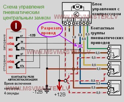
To connect the pneumatic central lock, you need to find in the car any of the three control wires, cut it and connect two wires from the alarm pattern I. It is more convenient to use the driver's door wire (according to the scheme blue). He goes out the door and goes down the left threshold.
We connect the alarm relay contacts according to the scheme presented here. Such a connection provides free passage of the signal from the driver's door to the compressor through the contacts of the alarm relay. In other words, we do not violate the correct operation of pneumatics.
When the alarm is armed, the relay for locking our alarm is triggered, as a result General the contact of this relay opens with normal closedcontact, "breaking" the control wire from the door and connects normally open contact connected to -12V. Thus, the alarm instructs the compressor to close the door.
Due to the fact that the pneumatic system is inert and it takes 1.5 to 3.5 seconds to lock all the doors and the contacts of the control wires switched to minus, we need to ensure that the alarm relay is held for the duration of this process, so that everything works as it should. The time for the control signal of the central locking alarm must be selected 4 seconds. Almost all alarms have this option, you need to study the instructions and select the desired time (4 seconds).
If this is not done, then as soon as the alarm relay returns to its original state, the circuit between the control wire of the drive and the compressor is restored, and if by this time the lock has not yet closed, the plus wire remains on the control wire and the compressor receives a command to open everything. As a result, the alarm system was armed, and the doors remained open.
It’s the same with disarming, only in the process the relay for unlocking our alarm is activated and it breaks up plus 12 volts towards the compressor, which starts the process of opening all doors.
Attention: It is very important not to mix up the two alarm wires connected to the control wire gap. If this happens, then when the relay is turned on, a short circuit occurs, and these are knocked out fuses that burned out in the track alarm and the relay stuck in it. The signaling needs to be repaired or replaced by another, so be very careful when connecting, we give voltage to the compressor side and not like otherwise !!!
 220
169
220
169
For the sake of completeness, consider the central lock of the VW GOLF III. In this example, we will see that the control of the compressor lock can be not only classic like that of the 124th, but also mixed.
The figure on the left shows the structure of the central lock VW GOLF III.- Pneumatic interior door drives
- Pneumatic trunk lid and gas tank flap
- Compressor central locking
- Air tubes connecting the compressor to the pneumatic actuators
The thing is that in Golf 3 you can control the central lock two ways.
 180
240
180
240
Note: If the lock is closed with a gray wire, it cannot be opened using black red the wire. If we use for management gray and green wires, then if there is a key in the ignition, you cannot close the car with a key fob.
When connecting an alarm to the Golf III central lock, the second method is preferable. The wires exit the door and are in the same connector. as the black and red wire, the picture shows how wires from the alarm are connected to them. To make sure that these are the wires we need, click the lock dog so that the stem in the driver's door can lower freely, take the car control, connect it to + 12V with a “crocodile”, and pierce the gray wire with a probe, the compressor motor should work and close the doors. We pierce the green wire with the control, the compressor engine should work and open the doors. Alarm outputs to control the central lock, we switch according to the scheme.
In addition to this, if you want the windows to close automatically when arming, you need to connect the alarm wire - (glass control) to brown gray to the wire. This wire comes to the comfort unit, which is installed behind the left kick panel at the feet of the driver and looks like a dual relay in one housing. The control over this wire is carried out by a minus and with a hold of the signal (while the minus is present the windows are rising, the minus is off - the windows are stopped).
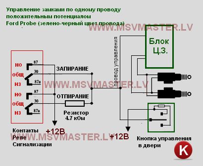
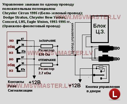
One-wire central locking control with positive potential
On the pattern-K and pattern-L shows the central locking of the car with positive potential control on a single wire. This single wire provides both locking and unlocking locks. Management on it is achieved by changing the level of positive potential. The desired level of the positive signal is set by the resistor, through which it is fed to the control wire.
This type of control is used on a 1995 Dodge Stratus, Ford Probe, Chrysler, New Yorker, Concorde, LHS, Eagle Vision 1993-1995 car.
 410
336
410
336
Ford probe
- The Ford Probe Automobile control wire is located under the left-side kick paneling and has a green-black color. Signallocking - positive impulse +12 V. Signalunlocking - +12 V positive pulse connected via a resistor 4.7 kΩ.
- Alarm connection pattern-K.
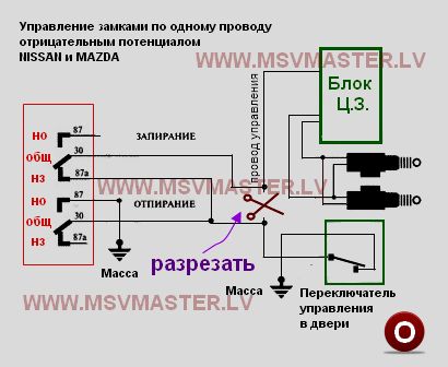
 One-wire control of the central lock by negative potential
 On the pattern-M and pattern-N Shows the central lock of the car with negative potential control on a single wire. This single wire provides both locking and unlocking locks. Management on it is achieved by changing the level of negative potential. The desired level of the positive signal is set by the resistor, through which it is fed to the control wire.
This type of control is used on some Mazda, Dodge Caravan, Plymouth Voyager, Chrysler Town & Country 1996 cars.
 410
336
410
336
- Car Control WireDodge Caravan, Plymouth Voyager, Chrysler Town & Country 1996 It is located under the skin on the left of the "BODY" connector of the unit and has the color White with a light green stripe. Signallocking 1.5 kΩ. Signal unlocking - negative pulse -12 V connected through a resistor 250 ohm.
- Alarm connection pattern-M.
 410
336
410
336
- Central locking carMAZDA(White-green wire)
- Signal locking - negative pulse -12 V connected through a resistor1 kOhm.
- Signal unlocking - negative impulse -12 V.
- Alarm connection pattern-N.
 410
336
410
336
Some Nissan and Mazda vehicles use single-wire control. where the Unlock signal is a negative pulse of -12V., and the locking is achieved by "breaking" the control wire.
For example, on a 1991 Mazda MPV, the color of the control wire is Green and White, you can find it in the connector of the lock control module behind the glove compartment.
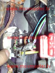
On Nissan 1991-1995 cars, this wire comes out of the driver's door and can have the following colors: orange-blue or orange-black, brown or brown-black, depending on the year and model.
You can find this wire using car controls. "Hang the crocodile" to the minus, we snap the dog of the driver’s door lock, turn off the trailer so that the car does not see that the door is open, close the central lock with the key. With a control probe, we pierce the alleged wire and if this is it, then the central lock will work and all the doors will open. To finally make sure of this wire, cut it, C.Z. should work and the doors should close. If everything is so, then in the wire break we connect the wires from the alarm to Rating 4.71
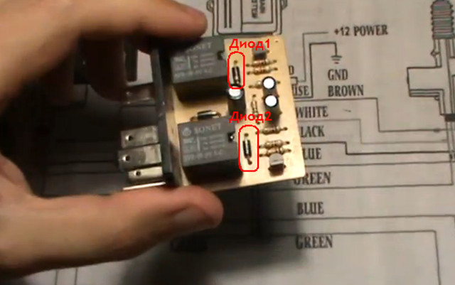
Here it will be considered how to repair the central lock installed in the car, more precisely, the lock control module. More often in publications this module is designated as follows: “BU TsZ”, which means “central locking control unit”. It is easy to see that it is a miniature box equipped with one connector with 6 or 8 contacts. And although the cost of such blocks often does not exceed 300 rubles, there is no need to rush with a replacement. Valuable details can be found inside the case - this is a pair of relays switching a current of 20 amperes. If the repair does not succeed, at least it will be possible to unsolder the relay.
Varieties of BU TsZ and connection
The control unit connector always contains 6 main contacts. Four of them are power (there is a significant current), and two more are signal. “Mass” is connected to the signal wires, and the locks are unlocked or locked. Further, all this is considered in more detail.
BU TsZ VAZ cars
If you see that more than 6 contacts are used, then there is no need to be surprised - all the rest of them are additional. By the additional contacts, by the way, control signals can go, in the absence of which it will not be possible to check the unit.
By looking at the connection diagram of the VAZ-2110 CZ, you can once again make sure that the main contacts are always 6:
So the block is connected in the "Ten"
It is necessary to correctly determine what to connect the power to (in the figure, these are pink and black conductors). Next, you need to find the conclusions going to the electric motors. Well, white and brown wires will often be managers. When the brown cord is connected to ground, 12 volts are applied to the motors for 0.8 seconds, and the polarity of this voltage corresponds to “locking”. The white cord is responsible for the “unlocking”, and the “mass” is never applied to both cords at once.
We disassemble the block, look for defects
Once again, we note that considerable current can flow through the cords connected to the unit. We are talking about two power wires, as well as the findings connected to the motors. The approximate value of the current strength is 20 A (a maximum of 15 goes in the Euro socket). And with such values, all the details are mounted on the PCB, which cannot but lead to the destruction of the “tracks”.
BU TsZ, printed circuit board
The foil track is covered with a layer of solder to increase its cross section. But, as you can see from the photo, ring cracks sometimes form, breaking the connection between the track and the terminal. A similar defect is quickly fixed by soldering, but this is only the beginning.
Checking diodes protecting transistors
The DC relay cannot be used if a diode is not connected in parallel with the magnet coil. This element, i.e. the safety diode, is usually located next to the relay case. So, finding it will be easy.
 Printed wiring BU TsZ
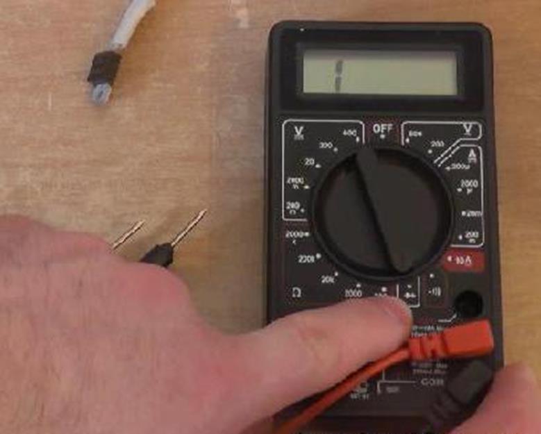
When checking in one of the connection options, the display should show “1”, in another - from 200 to 500 mV.
Suppose at least one of the diodes conducts current in both directions or does not conduct at all.
Then, in 99% of cases, you can do this: unsolder the relay and, with a clear conscience, discard the unit, or rather, what is left of it. The fact is that in the event of a breakdown or rupture of the diode, all transistors fail. However, you can give the unit a last chance: by installing serviceable parts to replace the old ones, you can check by connecting the unit “in place”. The value of the element called "diode" in this case is not important. The main thing is not to make a mistake with the polarity (it is indicated on the board).
Replacing failed electrolytic capacitors
A part called "capacitor" is a cylinder having two taps on one side. You can simply check the performance of the capacitor: just look at its cover and make sure that it has not lost the shape of the plane (not “swollen”). If the last condition is not fulfilled, the capacitor is replaced, observing the polarity of the connection.
 Two parts need to be replaced.
 There are positive and negative conclusions, and on the imported part, the “minus” is indicated by a strip on the case.
Choosing a new capacitor to replace a defective one, you can not violate the following requirements:
- The rated voltage must be 16 volts or more.
- It is strictly forbidden to install a part of a larger capacity than provided: you will get a response time increased by several times (instead of 0.8 seconds it will become 1.6). This will adversely affect the durability of door mounted actuators.
- The size of the new part must match the printed circuit board. Strange as it may seem, this requirement is the most difficult to fulfill.
If you carried out the repair in accordance with the tips outlined here, check the unit for short circuits. Connect the “Krona” from the tester to the power terminal (positive terminal), and the negative terminal to ground. Try to apply a "minus" to each control wire - the relay should click. However, the latter property is not typical for all blocks, but only for the most “primitive” ones. Usually, for control unit operation, a lot of control voltages are needed.
 Scheme of connecting BU "Grant"
 This is how you can protect yourself from unpleasant consequences. Any control unit, even a faulty one, acts as a “buffer” between the battery and electric motors. If the repair is performed with errors, you will receive a broken central lock (and even then, not always). And the actuators themselves, as is easy to understand, will remain unscathed in any case.
The entire instruction on the video
Since the statistics on theft of vehicles in our country is quite sad, and so far do not want to improve, each car owner seeks to provide his car with a protection system. In this role, complexes that are different in principle of operation can be used, and one of the simple but reliable systems that are invariably present in today's cars is the central lock. It guarantees closed doors, trunk, hood, windows and fuel hatch at the same time.
Installation of the central lock is possible with your own hands, and it represents an electromechanical system for controlling and locking central doors. It can be activated both by a simple turn of the key, blocking the doors for the duration of the movement, and by means of the remote control. The latter can be a separate unit or be integrated into a key. If the car has power windows, the central lock can close them automatically.
Can I connect the central lock myself
Connecting a central lock will require a layman to put a lot of effort, patience and time, but the result will be excellent. Before connecting the central lock, it must be purchased. At this stage, savings are extremely inappropriate, because poor-quality, suspiciously cheap products are unlikely to meet any safety requirements, and there is no guarantee that the lock will not jam during operation. It is also not recommended to purchase such a device from hand.
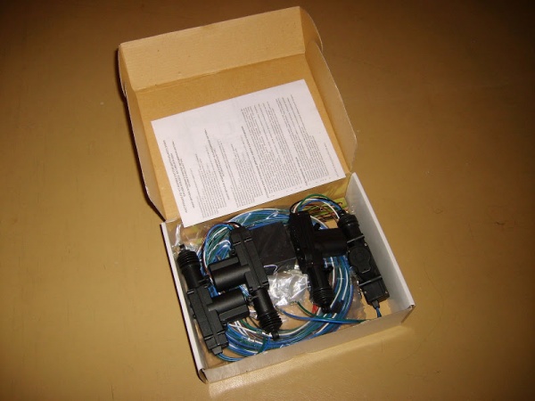
The standard lock kit that should be checked upon purchase includes the following items:
- control unit for the entire system;
- four activators, each of which is equipped with a set of mounts;
- set of wires;
- two remote controls, which can be in the form of folding keys.
Attention! All new wiring, which you will need to create when installing the central lock yourself, must be placed in separate corrugated tubes - this will protect them from accidental damage.

Central locking control unit
For this entire security system, the central locking control unit is its main element - the “think tank”. In its execution, it can be either simple or extremely complex, working on the basis of modern microprocessors. A block can consist of one case, in which all its elements are combined, but recently, more and more often you can find a multi-case design. This was made possible thanks to the creation of CAN-buses, and allowed to place blocks in opposite parts of the vehicle, which increases the reliability and safety of the system.
The central locking unit is connected by wires to all sensors and actuators available in the system. Receiving and analyzing signals from sensors or the control panel, it transmits control signals to electric drives that lock / unlock doors or windows. If the car owner wishes, the lock control unit can also work with car turn signals, giving light signals about closing / opening doors. Since this element plays the main role, only the vehicle owner can know where the central locking control unit is installed - this will prevent it from being turned off or damaged by intruders.
Sensors and buttons of the central lock
The central lock connection scheme necessarily includes a lot of sensors, due to which the correct operation of the entire system is ensured.
Actuators
Actuators, or actuators, can be used not only in electromechanical locks, but also in central locks with pneumatic control. In the latter case, they will operate on compressed air.
Electric drive
It is a plastic case in which an electric motor and gearbox are located, which converts the rotation of the motor into translational motion. Depending on the design, the electric drive may include one or two motors.
Pneumatic drive
It features a more complex design. It consists of a housing in which a membrane with a rod is located. A fitting for supplying compressed air is mounted in the housing itself. When air is supplied to the sealed case of such a switch, it switches to the “closed” position, when aspirated, the rod retracts and the lock opens. In more advanced pneumatic locks, solenoids are additionally installed - such a drive cannot be opened, for example, with a ruler.
How to connect a central lock with your own hands
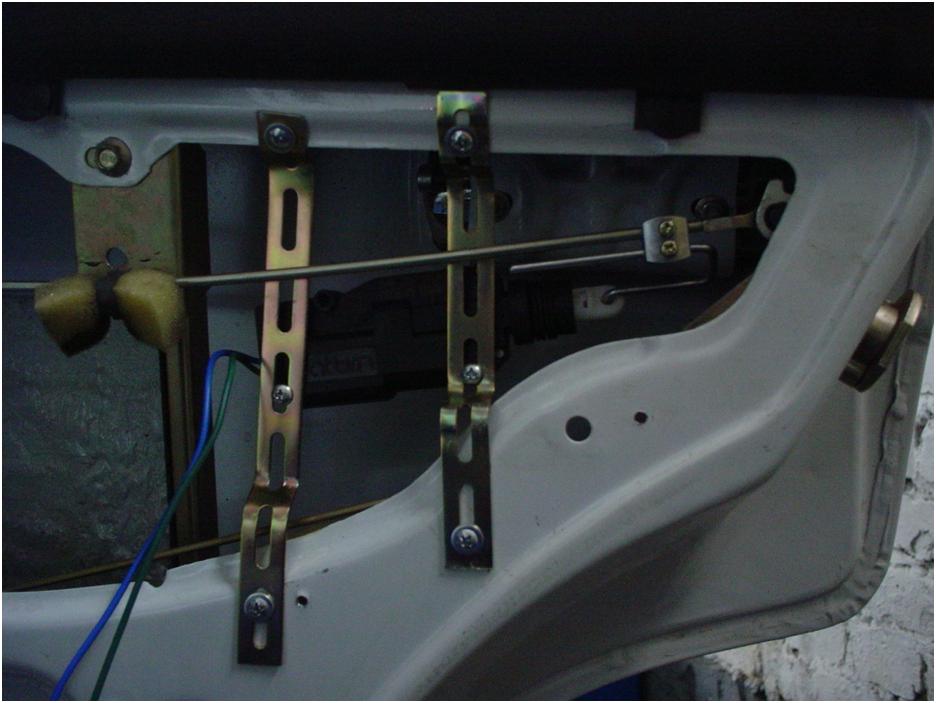
Connecting a central lock is best to start with the installation of actuators. Optimally, if they are located on all four doors of the car. To install them, you will need to dismantle the door trim and sills. Even if the car left the factory without a central lock, as a rule, the holes for the wires of this system are already provided by the design. If they are not there, they will have to be drilled on their own. It is better to start work from the driver's door, where the main central locking will be located. One of possible schemes Connection demonstrated on video:
Each lock is fastened with self-tapping screws, and its clamps need to be fixed to the rods of the manual block of the native lock. After that, you need to check the performance manually, making adjustments if necessary. After the fit made on each door, you can proceed to the placement of wires. From each actuator there are two pairs - two to the mass, and two to the castle itself. All wiring, placed in corrugated insulation, is attached to the door trim with plastic clamps.
After completing this stage of work, all the output wires are switched with the central control unit, the location of which is thought out in advance. It is unreasonable to give any advice on the placement of the unit, since there is no single standard here, and each car owner himself solves this difficult question. After connecting and checking the operability of the entire system, you can screw the casing into place.
After self-made installation of the central lock, it is required to conduct routine inspections of the entire system with a frequency of once every six months. All locks, the central unit, wiring and its connection points are subject to inspection. All areas with traces of oxidation are cleaned and isolated again. To facilitate the work, the wiring can be called by the tester, but this will not allow you to check the status of the contacts.
Therefore, it is better to allocate time for dismantling the casing and visual inspection. Since after the installation of the system it becomes part of the onboard power supply, maintaining it in good condition is also an important point in the operability of the central lock. Particular attention should be paid to additional electrical equipment connected to a common network, as well as the state of the battery and generator.
It’s not enough just to buy a new car. You must immediately make it safe and comfortable to use. It is not necessary to install thousands of options and additions. You can start with the simplest, for example, even a central lock without an alarm will make the operation of the machine more comfortable. And to some extent complicate the task of crackers. And you can put an anti-theft tool a bit later. If at the initial stage there is not enough money or time, it is quite possible to get by with this straightforward option. Moreover, its installation is pretty transparent.
Preparing for a central gate installation
The complexity of the installation depends on the brand of car. But, in fact, cases when something needs to be filed and drilled for a long time are rare. They mainly include long-lived cars, which are at least thirty years old. In most versions, the car is already prepared for the installation of the central locking system. It remains only to put the kit in place. Well, the second side of the question is the set itself. If you don’t want to dig for a long time, buy universal locks. Installation is simple and you will find plenty of information on them.
What is in the basic kit?
We take the simplest universal kit. Management, in our case, will be carried out with a special key fob. Usually there are two. There is an option when the system will be triggered by turning the key in the driver’s door lock. You can also bring a special button into the car. This additional option is very pleasant if the door needs to be locked during the ride. It is not always convenient to use the remote control.
So, we get a universal lock kit, which in most cases includes:
- Four motors. Will be mounted on the door. One of them with four wiring - to the driver's door;
- Control block. To him we, subsequently, will bring all the wires;
- A set of wires of the desired length. If you feel that they are not enough, buy additional ones right away;
- Trinkets, trims, screws, etc.
 central locking
 Necessary tools for work
Now we are assembling a tool that is useful to us in work, if there are no holes for fastening the motors in the doors, then prepare a drill with a drill. Still necessary: \u200b\u200bscrewdrivers, a screwdriver, knife, corrugated tubes (wires are laid through them to avoid grinding and the effects of external factors on the wiring) and electrical tape. We will rewind all open sections of wires with tape in order to avoid their contact with metal parts of the body.
The last thing to do before proceeding with the installation is to remove the casing and dustproof curtains from all doors. Determine the place where you will fasten the mechanism so that it does not interfere with the operation of the windows. If necessary, you will have to make an additional bracket.
Central locking
All necessary preparations have been made, and you can begin to work. We fasten the engines to the doors, remember that we put a motor with four wires on the driver’s door. We install the control unit there.
Wiring diagram
After installation, we check the correctness of interaction with the lock rod, which is responsible for opening and closing the door, and the smooth operation of the lock itself.
Important! Before working with wires, disconnect the battery to avoid dangerous situations!
We pass to the wires. Pull them from each motor to the control unit. Think in advance how to drag the wire from the rear right door. You can use the space under the seats. We connect them accordingly with the circuit and carry out a check. To do this, return the battery to its previous state. If any malfunctions are found, check first for correct connections. The outputs for plus and minus may be confused. When checking, it is better to be inside the car or not close the doors. As soon as you restore the battery, the locks should work automatically.
 Installed and connected motor
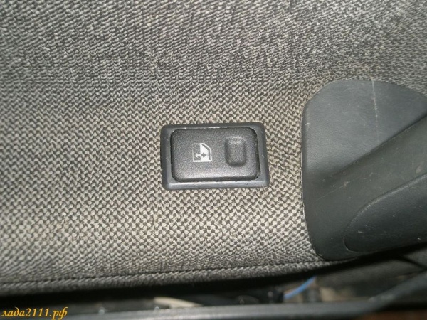
 If you still want to make the lock control button, prepare the missing parts in advance. Additional wire and button. It can be embedded in the dashboard. Buy any button, for example, for a window regulator.
Installation of the central locking control button
We are looking for black, brown and white wires under the side panel and connect to them. Alternatively, you can stretch the wires and connect with a bunch of electricians from the central lock of the driver's door. And the rest of the connection is performed according to the scheme.
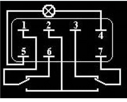 Connection diagram of the central locking control button
 Connection diagram of the central locking control button
It is absolutely not necessary to make this button on the panel. Again, it all depends on the convenience. You can place it in the space between the front seats, if there is the necessary electrics. As an option, the button can be embedded in the armrests on the doors.
The trunk can also be connected to the central lock. Which, incidentally, will also significantly save your time and nerves. If you have a janitor on the rear window, then the necessary electrics are already stretched, and connecting is not difficult. The main thing is not to forget that the central lock still can not protect your car one hundred percent. Such options must be used comprehensively and, of course, set the alarm.