Ervist - explosion-proof equipment, industrial, special
WELCOME TO THE ERVIST WEBSITE!
Our site is dedicated to equipment and services in the field of safety systems and electrical engineering.
The section of the site presents electrical explosion-proof equipment manufactured by domestic and foreign manufacturers. This is the most comprehensive collection of descriptions of devices, materials and components for creating security systems for fire, explosive and industrial facilities. Our site presents the latest news and achievements in this area.
At higher temperatures, there is a shorter wavelength and vice versa. In addition, infrared radiation passes through smoke, but no light. Because it does not respond to the sun and lamps. Even the sun and lamps generate infrared thermal radiation. However, the flame is different in that it pulsates with its own frequency, which is from 3 to 30 Hz. However, direct exposure to the sun or other intense lights blinds the detector and should be avoided.
Both exits cause alarm after a certain delay and return to rest as soon as the fire ceases. The delay time is usually set to 5 seconds, but varies from 1 to 10 seconds. The field of view is a 90 ° cone, but more than 90 ° the detector still sees with reduced sensitivity, and shady areas behind obstacles are also visible for reflection. A small accumulation of dust or dirt on the detector window does not significantly change its functionality, since thermal infrared radiation is attenuated much less than light.
The site section presents products that were developed with the participation of ERVIST specialists in collaboration with leading enterprises in the Security Systems industry. Our company has a priority sales right for these products or has an exclusive discount from the manufacturer.
Schedule for the fall semester 2017 webinars
| date | Topic |
| September 12, 2017 | Climate protection and switching equipment from the company NPO Spectron. (NPO Spectron) Registration for the webinar |
| September 26, 2017 | A new series of control modules for the MTS thermal cable from the company "Plasma-T". (Plasma-T LLC) Registration for the webinar |
| October 3, 2017 | FIREFLY’s unique spark suppression system technology and a new standard for quick extinguishing fires. |
| October 17, 2017 | Radio-channel automatic fire extinguishing system "Garant-R" from the company "Eternis". Standard solutions and unique new features. |
| October 31, 2017 | Aspirating fire detectors and WAGNER / TITANUS systems for the protection of Data Processing Centers (DPCs), electronic libraries, archives, server rooms. |
| November 14, 2017 | Novelties of the equipment of 2017 from the SMD company. |
| November 21, 2017 | Modules of automatic fire extinguishing TRV Garant-160 and Garant-100 from the company Eternis. |
| December 5, 2017 | Fire detectors "Radar-Ex" and "Expert-Shield" are the main novelties of 2016-2017. from the company ERVIST and partners. Detection of fires at an early stage. |
| December 12, 2017 | All new products of 2017 from the company NPO Spectron. Summing up the year. (NPO Spectron) |
The site section presents the equipment of leading Russian manufacturers for creating security systems at industrial facilities, fire and explosive facilities, facilities with difficult operating conditions.
Frequent regular cleaning is not required if no dust has fallen. Even smoking does not make the detector blind, which can also prevent fire in a fire with a lot of smoke. This device simulates a flame inside the detector, so that the response of the sensor is “as if” in the presence of a fire. The telelet consists of an incandescent lamp and a modulator circuit that generates an infrared button output in front of the Sensor Control can be set manually at a distance or can be automatic continuous. The response to the test detector is a short half-second excitation every four seconds for the duration of the test.
We also supply foreign equipment:
Company WAGNER (Germany) - the European leader in the development and supply of aspiration fire detectors and systems under the brand name Titanus . Aspiration fire detectors and systems are the means of the earliest detection of fires, they are especially relevant at facilities with great material and information values, such as: bank vaults, depositories, data centers, digital libraries, server, warehouse terminals, storage rooms, archives, libraries, museums, transportation facilities, including underground, fire hazardous and explosive facilities.
These short beeps are recognized by the control panel compared to a “permanent fire alarm”. Typically, the detector is mounted vertically in the center of the protected area, so that a 90 ° conical field is used as efficiently as possible. If the ceiling is low, corner mounting is an ideal alternative. In this case, the height can be a third of the side. Avoid direct exposure to the sun and strong light bulbs that blind the detector.
Unlimited safety: special fire detectors
Install a protective cover or visor if necessary. Avoid mounting on housings or vibration motors that may cause false alarms. They can operate with maximum reliability even in the most difficult conditions. They selectively ignore heat, cold, soot and moisture and accurately report important events. Special fire detectors are used, for example, in tunnels, cold stores and laboratories, as well as in museums or computer centers.
Xtralis Company (Australia) - a trademark - is an innovator in the field of ensuring the safety of objects of special importance. Xtralis is the world's largest manufacturer of suction smoke detectors. Today, the most respected companies in the world and leading government organizations rely on VESDA technologies for the fire protection of various facilities. VESDA has developed the most efficient fire safety systems to date with early fire detection. VESDA does not register a fire, it detects it!
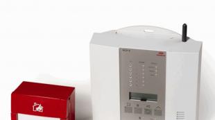
Decentralized Modular Security System
Connecting to global integrated systems optimizes efficiency and usability. Temperature sensor: its sensors record and immediately report on temperature thermal temperature sensors: record hot air, a rapidly spreading infrared linear fire detector: it detects the opacity crossed by infrared rays and caused by a heat or smoke exhaust system: it checks whether the charge air contains smoke video surveillance curtains: digital image analysis to detect fire and smoke. It consists of control panels, new generation alarms, fire detectors and new and innovative operator panels.
ERVIST ”since 2006 is a partner in sales and maintenance of equipment in Russia.
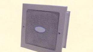
MEDC is a trademark known worldwide for its high quality standards and leadership in the market of equipment for explosive and industrial facilities.
MEDC - this is the equipment for creating warning systems, alarm systems, communications, process control systems. MEDC equipment is of high quality, reliability, ease of use and maintenance. The most difficult operating conditions for equipment are present in the oil and gas and chemical industries, which means that the equipment used must comply with the most stringent safety standards.
The loudspeakers fully meet these requirements: DB4L-8, DB4L-15, DB4L-25, DB10-8, DB10-15, DB3L sirens and MEDC SM87HX flashlights.
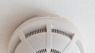
Intelligent Smoke Detectors
The system is adaptable and can be used for both large and small installations. Better smoke and temperature composition, connected sensors, optimized smoke penetration behavior and new signal filters ensure maximum fire detection accuracy. Even with comfort and economy, a new generation of detectors creates new primates. Based on these values, it determines the optimal sensitivity for each location and is adjusted according to environmental conditions.
Thermocable (thermal linear fire detector) manufactured by the company Protectowire Inc. It is a cable that allows you to detect a heat source anywhere on its entire length, i.e. the thermal cable is a single continuous sensor.
The PHSC thermal cable is widely used in oil and gas enterprises, in the metallurgical and chemical industries, in manifolds and cable channels, in auto and railway tunnels, where the use of traditional fire detection equipment is difficult. Explosion and fire hazard areas, the presence of moisture, dust, increased pollution, low temperatures or aggressive environments - in these conditions, the PHSC thermal cable has invaluable advantages.
Suction smoke detection
Depending on the needs, various units can be installed. Ease of assembly is facilitated by bayonet technology, is safe and tested. Light from smoke particles enters the detector's sensor, which turns it into an electrical signal. It not only constantly monitors the temperature in the room, but also accurately measures the speed with which it rises. If the programmed alarm threshold is exceeded or the temperature rises faster than the fixed limit, the detector sends an alarm to the control panel.
- Alarms for smoke and heat are reported separately.
- The heart of this heat sensor is the temperature sensor.
The company's products are high-quality flashlights of various designs used in hazardous areas, at the enterprises of the oil and gas, petrochemical, mining industries, fire and rescue services. MICA flashlights are characterized by ease of use, reasonable compactness, and long battery life. Optimum prices and stock availability make MICA flashlights available to a wide variety of consumers.
Always in this room is a fan that draws air in the pipeline and an electronic evaluation circuit. Sensitivity levels, lengths and branches of the suction pipes can be adapted to the environment that needs to be protected.
- He discovers the principles of fire with great sensitivity and timeliness.
- It provides maximum response speed.
- It has different levels of sensitivity.
- Optimal filtering of noise factors by combining fire parameters.
- Great job even in critical conditions.
The page of each device is supplemented with background technical information: passports and user manuals, certificates.
In chapter WEBBINARIAN ARCHIVE you can easily find videos of all webinars held in the program ERVIST FORUM - On-line professional discussions and promotion of advanced products and solutions.
The processor constantly analyzes the current pressure values \u200b\u200band, when the default threshold is exceeded, instantly triggers an alarm. The system is completely self-controlling: at certain intervals, the pressure control engine generates a certain excess pressure inside the tube probe. If the increase in recorded pressure does not match the programmed normal value, the processor will signal an error.
Garages, underground garages, cockpit and transport channels Gas and heating systems, plants and chemical plants Logistic and distribution centers Fuel fields. In some particularly adverse environmental conditions, even a measuring device can be useless.
The page is dedicated to the design, installation and maintenance of security systems. In the near future we plan to acquaint our potential customers with specific technical solutions on this topic.
11.04.2013, 14:28
The sensors are enclosed in an inner shell and an outer shell; information is transmitted through a special tire system protected by an international patent. Tunnels automobile, railway or meter Tires and underground garages Pipes and pipelines, gas and thermal Chemical plants and plants Industrial buildings and warehouses Production lines, oil refineries and mills Logistic and distribution centers. There are systems for installation in homes, offices and institutions of various types of companies.
Discovery is a core aspect and combines three categories of devices. Smoke detectors are susceptible to particles of combustion products suspended in the atmosphere, heat and temperature sensors are able to detect a sharp increase in temperature; flame detectors capable of capturing radiation from fire. Contact us for more details. Suction smoke detection systems are the most popular and thanks to their innovations they can achieve great efficiency. In particular, plants can quickly act on a hazard, limiting its effects.
As part of the course articles .
I. Neplohov
ph.D., Technical Director of the Center-SB Business Group,
N. Kulikov
head of Technical Department, LLC NPF Polyservice
Fire flame detectors are unique as a class. Unlike almost all other types of fire detectors, which are intended only for indoor installation, flame detectors allow you to protect the outer areas of a large area, installation and storage, including in hazardous areas. They provide the shortest possible time for the detection of tanning of materials that do not have a smoldering stage, such as flammable liquids and plastics. The principle of operation of fire flame detectors and specific operating conditions determine the features of their design and placement. Flame detectors more than 10 years ago, during certification according to air safety standards 72-98, began to pass tests on standard test sites TP-5, TP-6, which give a reliable assessment of their effectiveness when working in real conditions, in contrast to other types of fire detectors still not held in Russia. The specifics of the use of fire flame detectors determines the low coverage of this topic in the industry press, although there is a constant increase in interest in this equipment.
In the case of the combustion principle, the fire detection system recognizes extraneous elements, signaling its presence with sirens or light pulses to inform the perpetrators of the danger. Various commercially available devices are capable of detecting the presence of smoke particles in the air of the environment in which they are located, as well as a change in temperature or flame radiation. This is an innovative fire alarm equipment.
Suction systems: history
Suction smoke detection systems are from the nineties. The first models were experiments based on the self-development of some technicians, and over time they reached a high level of quality. Standards and compliance with European standards allowed the equipment to spread and follow the path of innovation using the most modern technologies.
DEFINITIONS
According to the current GOST R 53325-2009 “Fire fighting equipment. Technical means of fire automation »fire flame detector (IPP) is an automatic fire detector that responds to electromagnetic radiation from a flame or smoldering fire. According to the operating range, fire flame detectors are divided into IPP infrared wavelength range, visible range and ultraviolet range. Any flame detector contains a sensing element - a converter of electromagnetic radiation into an electrical signal - which responds to electromagnetic radiation of a flame, respectively, in the infrared, visible or ultraviolet wavelength range. Also identified are multi-range flame detectors that respond to electromagnetic radiation from a flame or smoldering fire in two or more parts of the spectrum of electromagnetic radiation. The infrared range includes electromagnetic radiation occupying the spectral region from the boundary of red visible light with a wavelength of 0.76 μm to the beginning of the range of microwave radiation with a wavelength of 1-2 mm. The entire range of infrared radiation, which is also called thermal radiation, for definiteness is divided into three sub-ranges: short-wave region with a wavelength of 0.74-2.5 microns, medium-wave region 2.5-50 microns, long-wave region 50-2000 microns.
In addition to ensuring plant conformity, the rule establishes three classifications for commercial products. Classes are called selective lights, depending on the types of fires that must be carried out by systems verified after their production. Intake smoke detection systems should be equipped with air flow sensors and enter the alarm system when the flow is faulty, recording a change, increase or decrease of 20%.
How does the suction system work?
The division of response classes. Suction smoke detection systems are based on the removal of air present in the environment where they are installed to protect it. They transmit the task through a network of tubes, collecting air, which is supplied to a particularly sensitive unit, which can detect a small amount of smoke present.
The ultraviolet range of electromagnetic radiation is located between visible and x-ray radiation from 380 nm to 10 nm and is conditionally divided into near ultraviolet from 380 to 200 nm and far from 200 to 10 nm, which is significantly absorbed by the atmosphere. Between them is electromagnetic radiation of the visible range, which is perceived by the human eye, with a wavelength of 380 nm (violet) to 760 nm (red). Nm, or nanometer, is one billionth of a meter, that is, 10-9 m, or a thousandth of a micron, 10-3 microns. The visible range in flame detectors is practically not used due to the significant level of interference created by various lighting devices.
As soon as smoke is detected, such a unit, using the principle of diffusion of light, activates the laser beam and directs it into the reflection chamber. Any combustion product, even in small quantities, causes the release of light pulses to signal a hazard.
How to connect the suction system
Meanwhile, it should be clarified that the suction system is part of a fire detection system. Intake smoke detection systems are typically built into buildings and are manufactured with other devices to discharge the function of fire. The greatest use relates to the industrial environment, hotel complexes, shopping centers, medical institutions and government bodies. In addition to flame retardant coatings to limit damage, equipment is used to provide quick intervention, which is usually assessed by firefighters who provide accessibility and insurance companies that are available with discounts on fire insurance.
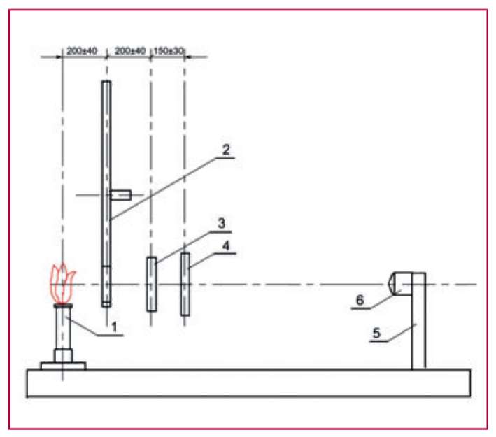
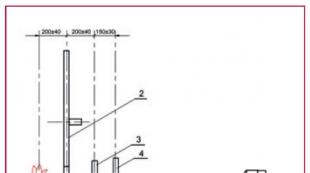
Fig. 1. The design of the optical bench
CLASS OF FIRE DETECTOR OF FLAME
According to GOST R 53325-2009, the flame detector must detect test fires TP-5 (combustion of a flammable liquid with smoke) and TP-6 \u200b\u200b(combustion of a flammable liquid without smoke). In accordance with Appendix H, 650 g of a mixture of N-heptane are used in the test site TP-5, in a pallet of sheet steel measuring 330 x 330 x 50 mm, i.e. an area of \u200b\u200bapproximately 0.1 m2. In the test center TP-6, 2000 g of ethyl alcohol is used in a pallet measuring 435x435x50 mm, respectively, with an area of \u200b\u200babout 0.2 m2. Moreover, depending on the maximum distance from which stable flame detection of the test sites TP-5 and TP-6 \u200b\u200bis still provided for no more than 30 s, a specific sensitivity class is assigned: 1st class - detection of foci from a distance of at least 25 m, 2nd class - from a distance of not less than 17 m, 3rd class - not less than 12 m and 4th class - not less than 8 m. Moreover, GOST R 53325-2009 states that the definition of the class of a flame detector should be made at statement of a specific type for production, and confirmed by certification tests x. The flame detector class must be specified in the technical documentation.
OPTICAL BENCH TESTS
A significant part of certification tests, for example, the repeatability of the sensitivity value from sample to sample, the stability of the sensitivity of the flame detector, solid angle of view, and protection from the background illumination of the sensitive element created by fluorescent and incandescent lamps are carried out in accordance with Appendix I GOST R 53325-2009 by flame methane burner when using the so-called optical bench.
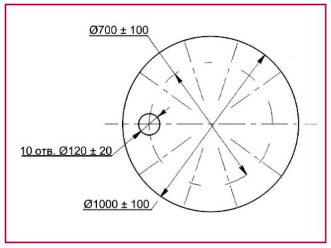
Fig. 2. Modulator disk
The optical bench is made in the form of a table having a length of 2.5 ± 0.5 m, a width of 0.5 ± 0.2 m and a height of 0.8 ± 0.2 m. A methane burner 1, modulator 2, neutral are mounted on the table attenuator 3, shutter 4 and stand 5 with flame detector 6 (Fig. 1).
The shutter 4 is a light-tight partition with a size of 0.4 x 0.4 m and is designed to form an impact on the detector flame of a methane burner at the required intervals without turning it off. Neutral attenuator 3 allows for a specific type of flame detector to select the required attenuation of flame radiation for measurements at distances within the optical bench. Modulator 2 is a rotating disk of opaque material with 10 holes (Fig. 2) with a diameter of approximately 1 m driven by an electric motor. It is designed to simulate flicker of a flame with a certain frequency and is used in testing fire detectors with appropriate information processing. The modulator is not used if the flicker frequency is not set in the detector documentation.
The detector is installed at a distance D equal to 1500 ± 20 mm from the burner so that the detector detector is in line with the radiation source and modulator. Illumination in the plane of the detector detector element from natural and artificial light sources should not exceed 50 lux. A shutter is installed on the line between the source and the detector, a methane burner is ignited, the detector is connected to a power source and / or fire alarm control panel. The energy P radiated by the source is measured by a radiometer and, during further tests, by adjusting the flame level, the measured energy P is maintained. The neutral attenuator is set to the maximum signal attenuation and, if necessary, the modulator is turned on. Next, the shutter is removed and the attenuator attenuation level is adjusted to achieve stable operation of the detector within the time set in the technical documentation for it, but not more than 30 s. During all further tests with a specific type of detector, the attenuator attenuation does not change.
By moving the detector along the optical bench, the so-called response point is determined - the maximum distance D between the burner and the detector, at which it stably operates for the time specified in the technical documentation, but no more than 30 s, which characterizes the relative level of sensitivity of the detector. According to the measurement results for 6 detectors sampled for random sampling of detectors, serial numbers are assigned: a detector with a maximum response point of No. 1, with a minimum of No. 6. Based on the maximum and minimum values \u200b\u200bof the distance D determined during the tests, the instability coefficient , characterizing in this case the repeatability of the sensitivity of the detectors:
To determine the stability of the sensitivity of the flame detector, six times the response points are determined under the same conditions with interruptions, for at least one hour, in between tests, the detector must remain on. Naturally, after each test, the detector is returned to standby mode. Also, the maximum and minimum values \u200b\u200bof the distance D obtained during these tests by the formula (1) determine the instability coefficient k, the value of which should not exceed 1.3. Accordingly, the ratio Dmax / Dmin should not exceed V173 ~ 1.14.
One of the most important characteristics, which is mandatory indicated in the technical documentation for the flame detector, is the solid viewing angle p, which characterizes the width of the detector radiation pattern and, accordingly, along with the detection range of the focus is used to determine the maximum value of the protected area. To determine the viewing angle of the flame detector under identical conditions, the response points are determined for the direction of the optical axis of the flame detector at an angle a to the direction to the radiation source, at a \u003d 0 °, ± 15 °, ± 30 °, ... "± a„ . The value of amax is defined as the half of the viewing angle p indicated in the technical specifications for this type of flame transmitter. From the maximum and minimum values \u200b\u200bof the distance D obtained during the test, the instability coefficient k is calculated, which should not exceed 2.0. Thus, the detection range of the foci at the boundaries of the detection region should be reduced by no more than 1.41 times compared with the maximum detection range, which is usually determined on the optical axis of the flame detector.
The resistance of the detectors to direct light created by artificial light sources is determined by the background illumination of the sensitive element with fluorescent lamps - at least 2500 lux, incandescent lamps - at least 250 lux. The test is carried out on an optical bench, the flame detector is previously incubated for at least one hour in the on state when the illumination in the plane of the sensing element (s) is not more than 50 lux. Then they turn on incandescent lamps for 1 s and turn them off for 1 s 20 times, then they produce a similar effect with fluorescent lamps, then they turn on all the light for at least 2 hours, and at the end of the test, the response point and instability coefficient k are determined, the value of which in this test should not exceed 2. Accordingly, the ratio of the detection range of the focus should change no more than 1.41 times. In addition, during the test, the detector shall not issue a “Fault” or “Fire” notice.
FIRE TESTS
For conducting fire tests, the flame detector is installed on racks at a height of 1.5 ± 0.1 m above the floor, and the test center is installed on the floor. The optical axis of the detector is positioned horizontally in the direction of the test site. The distance between the center of the test site and the base of the racks is set depending on the class of the flame detector indicated in the technical documentation. In the tests, the test sites TP-5 and TP-6 \u200b\u200bare sequentially used. The initial temperature of combustible substances shall be 25 ± 10 ° С. The air flow velocity at the installation site of the test center shall not exceed 0.2 m / s. Illumination in the plane of the sensitive elements of the IPP should not exceed 50 lux. Lightproof partitions are installed between the flame detector and the test site near the detector. Light the test site. After 30 s, the partitions are removed and the detector is exposed to the radiation of a flame, first of one, then of another test site for a time set by the manufacturer in the technical specifications, but not more than 30 s. The detector should give a “Fire” signal when exposed to flame radiation from one or the other test site.
NPB 72-98 AND GOST R 53325-2009
The basic requirements and test methods for flame detectors according to the new GOST R 53325-2009 are slightly different from those given in the previously existing safety standards 72-98. So, according to NPB 72-98, 8 samples were tested, 6 samples are being tested, 4 samples passed fire tests before - 2 with maximum sensitivity and 2 with minimum, now only 1 sample, and for some reason not with the worst, but with 4 th sensitivity. Direct light tests were carried out earlier on one of the most sensitive detector, now they are carried out on 5 samples, but on all but the most sensitive !? In addition, during these tests, the allowable instability coefficient from 1.6, according to NPB 72-98, was increased to 2 in GOST R 53325-2009. For some reason, GOST R 53325-2009 did not include sulfur dioxide exposure tests (corrosion protection tests) for broadcasters intended for use in rooms with aggressive environments, as well as the requirement for the degree of protection of the shell, which is in the airbag 72-98 was not lower than IP41.
It is positive that the viewing angle is now measured in 2 samples, and not in one, as was the case with NPB 72-98. In addition, fire safety requirements have been introduced in GOST R 53325-2009, according to which during normal operation of the detector and operation in the event of a malfunction, none of its design elements should have a temperature higher than the permissible values \u200b\u200bestablished by GOST R IEC 60065 (Clause 4.3 ) Before conducting fire safety tests, an analysis of the electrical circuit and the design of the fire detector is carried out. In the analysis process, a possible restriction of the power supplied to the fire detector from the power source is taken into account, and if the supplied power is limited to no more than 10 W, then the test is not carried out. Otherwise, expertly determine the most dangerous possibility of violating the integrity of the fire detector (short circuit or open circuit of external and internal circuits) and conduct tests according to the method GOST R IEC 60065 (clauses 4.3, 11.2).
For autonomous flame detectors, GOST R 53325-2009 introduced a check of the sound signal level, the value of which at a distance of 1 m should be at least 85 dB for at least 4 minutes.
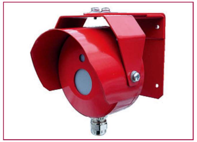
Fig. 3. Example of a dual-band IR + UV flame detector
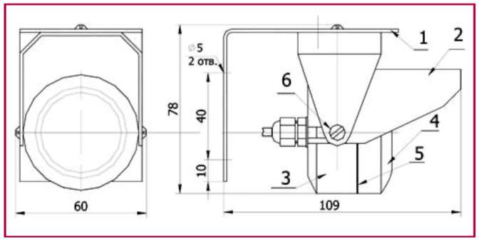
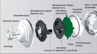
Fig. 4. Flame detector design
1 - bracket;
2 - visor;
3 - bottom of the body,
4 - cover;
5 - sealing ring;
6 - the screw of fastening of the case.
INSTALLATION REQUIREMENTS
In accordance with section 13.8 of the Code of rules SP 5.13130.2009 “Fire protection systems. Automatic fire alarm and fire extinguishing installations. Design Norms and Rules ”, fire detectors should be installed on ceilings, walls and other building structures of buildings and structures, as well as on technological equipment. If smoke is possible at the initial stage of a fire, the distance from the detector to the ceiling must be at least 0, 8 m. In addition, the placement of flame detectors must be carried out taking into account the exclusion of possible effects of optical interference. Pulsation type detectors should not be used if the burning surface area of \u200b\u200bthe fire source can exceed the area of \u200b\u200bthe detector control zone within 3 s.
The control zone should be monitored by at least two flame detectors switched on according to the “I” logic circuit, and the location of the detectors should provide control of the protected surface, as a rule, from opposite directions. It is allowed to use one fire detector in the control zone if at the same time the detector can control this entire zone and the conditions of clause 13.3.3, b), c), d) are fulfilled. The area of \u200b\u200bthe room or equipment controlled by the flame detector should be determined based on the value of the detector’s viewing angle, sensitivity in accordance with GOST R 53325, as well as the sensitivity to the flame of a specific combustible material given in the technical documentation for the detector.
CHARACTERISTICS AND CONSTRUCTION FEATURES
Accordingly, manufacturers of fire detectors of flame in the technical documentation provide information on the detection range of standard foci of test fires TP-5 and TP-6, as well as foci of other combustible materials, which allows the consumer to optimize the choice of detector type. The characteristics of the detectors are determined not only by the selected range, but also by the method of forming the radiation pattern. In practice, a large magnitude of the viewing angle is not always required; control of a certain area and blocking of signals from other parts of the area are often required. When using Fresnel lenses, a narrow-angle radiation pattern can be formed with a corresponding increase in sensitivity. Moreover, to ensure the possibility of operation of the detectors in difficult conditions, in the presence of dust, sand, wind, temperature extremes, etc., the optical elements of the flame detector are made of sapphire, not glass.
For example, if a flame detector with a solid viewing angle of p \u003d 60 ° provides stable operation from exposure to radiation from test sites TP-5, TP-6 \u200b\u200bof at least 17 m, then a flame detector with a solid viewing angle of p \u003d 12 ° has a detection range of TP -5 increases to 60 m, and the test site TP-6 \u200b\u200bto 50 m. Such a flame detector from a distance of 25 m detects burning sites of kerosene, alcohol and heptane with an area of \u200b\u200b0.0225 m2 (150 x 150 mm) and does not respond to interference outside the zone detection.
To enable the flame detector to adapt to various operating conditions, the flame detector may contain additional adjustment elements, for example, a THRESHOLD potentiometer, for adjusting the sensitivity of the detector by selecting the number of threshold exceeded Nu in a given time interval t.
In hazardous areas this time should be selected as short as possible; in rooms where smoldering fires are possible, the maximum time is set. For most industrial and residential premises, this time can be set in the range of 2-4 s. By changing the position of the THRESHOLD potentiometer slider, the analysis time can be adjusted from 1 to 8 s, and the number of threshold exceeded from 3 to 16, respectively.
For effective operation in real conditions, the flame detector must meet a significant list of additional requirements. So, for example, the detector for outdoor installation should have a high degree of protection of the shell, of the order of IP65, a wide range of operating temperatures, maintain operability during rain, snow, fog, dust, etc. The flame detector must have a sophisticated information processing algorithm to eliminate false signals in the presence of sun glare, flashing beacons, etc.
A significant reduction in the probability of false alarms can be achieved by using multi-range flame detectors that analyze electromagnetic radiation in several parts of the spectrum. For example, the spectral characteristics of sources in the ultraviolet and infrared ranges are isolated and analyzed (Fig. 3). On the other hand, in certain conditions, the “Fire” signal generation logic can be used when radiation is detected in any of the ranges - this algorithm expands the number of types of detected foci and reduces the time of fire detection. To select the logic of operation of a multi-range flame detector, corresponding adjustment elements are provided, usually in the form of jumpers.
Often, the operability of the fire flame detector is monitored with the formation of a "Fault" signal to the control panel in a separate loop and LED indication. Moreover, the voltage value of the detector is usually simultaneously monitored, therefore, additional elements are not required to control the power loop.
The requirements for the installation of a flame detector determine the design features - it is, as a rule, a sealed metal case, the presence of pressure glands, a mounting bracket with elements for adjusting the position of the detector (Fig. 4).
In conclusion, it can be noted that, unlike most other types of fire detectors, the development and testing of flame detectors is based on the detection of real foci, standard and non-standard, including reduced sizes. A significant amount of certification tests of fire flame detectors using a methane burner and conducting fire tests on standard test sites TP-5 and TP-6 \u200b\u200ballow us to control the main technical specifications declared by the manufacturer, which greatly simplifies the choice of detector type for a particular object.