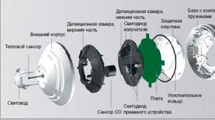
Satellite TV no signal on all channels. The practice of repairing satellite TV tuners
The article provides typical and once encountered in the author’s practice malfunctions of satellite television (STV) tuners and methods for their elimination. Since many tuners are designed according to similar schemes, the defects of some models are similarly manifested in other devices. Therefore, it will be very useful to have an idea of \u200b\u200bthe symptoms of defects and methods for their elimination. It should be noted that the material contains hardware malfunctions of the tuners. Due to the fact that many of these defects can occur due to damage to the microcontroller control program, you should first try to repair it, as described in.
ARION AF-1500E
No picture or sound
On-screen display (OSD) is displayed, the voltage of the external converter is normal. Oscilloscope monitoring of the TS MPEG-2 transport stream signals from the BS2F7VZ0184 channel selector showed that they do not pass through the resistors RA101, RA102 to the STi5518 decoder chip. After soldering the resistors, the defect was eliminated.
ARION AF-1900CI
No image and sound, OSD displayed
At the output of the U301 decoder (STi5518) (vyv. 32) the video signal is present, and at the output of the U721 video switch (AK4702VQ) (vyv. 3, 46) - is absent. The supply voltage of the U721 chip (+5 and +12 V) is normal. After replacing the U721, the fault was resolved.
ARION AF-1900CI
There is sound, there is no image and on-screen menu
Checking the +14/18 V voltage injected into the drop cable to power the external converter showed that it is normal when the drop cable is disconnected and is very underestimated when it is connected. The defect is eliminated by replacing the voltage regulator U151 (LM317) in the voltage generation circuit +14/18 V.
ARION AF-8110EC
When you turn on the tuner in the network, it does not switch to standby mode
The voltages generated by the tuner power supply are normal. Checking the Flash memory U381 (HY29LV160ATTC-90) showed a mismatch in its contents compared to the reference firmware. Writing a working firmware in U381 temporarily restored the tuner. It turned on normally at the first start, but after entering standby mode it became uncontrollable. Soldering of the Sti5518 decoder and Flash-memory, as well as control of the connections between them did not lead to positive results. The performance of the tuner was restored after replacing the Flash-memory and writing the reference firmware to it.
ARION AF-8200CI
The defect is manifested in the periodic appearance of RF noise components in the soundtrack
It was eliminated by replacing the EC4 capacitor (10 μF x 16 V) in the WM8725 DAC circuit. In addition, an electrolytic capacitor with a capacity of 100 μF x 10 V was connected in parallel with C1 (0.1 μF), which improved the sound quality of the broadcast programs.
COSMOSAT 7400
The mains fuse A1 (2 A) has blown, the key transistor Q1 (MJE13003), the PWM controller U1 (THX201) and the zener diode DZ1 (6.2 V) have also failed. Diodes D1-D4 are working. Replacement of these elements led to the restoration of the tuner. The Q1 power key transistor has been replaced with a more powerful type MJE13007.
COSMOSAT 7400
The tuner does not turn on, the voltages generated by the tuner power supply are normal
The supply voltage at the STi5119ALC decoder (3.3 V) is absent, the resistor R2 (1 ... 2 Ohms) is open. Since the resistance between the 3.3 V power pins of the decoder chip and the circuit ground was unity Ohms, it was replaced. After replacing R2, the device is restored to working condition.
DIGI RAUM DRE-4000
The defect arose as an irregular occurrence of a short circuit message in the drop cable
After turning the device off / on, the message appeared again after a short time. The defect is eliminated by replacing the C68 capacitor (4.7 μF x 50 V).
DIGI RAUM DRE-5000 (applicable to DRS-5001 and GS-7300 models)
The oscilloscope’s monitoring of the TS (Transport Stream) CLK, STR, VLD clock signals and D0-D7 data signals at the output of the channel selector showed that the data line has a log. "1". Testing the resistance between the ground and the pin. The 26 (CP_BYP) STB6000 RF converter in the channel selector showed a short circuit. After replacing the STB6000, the tuner is now operational. If the measured resistance is several kOhm, the defect is eliminated by soldering the STB6000. A similar defect is found in tuners whose channel selectors are made on this chip.
DIGI RAUM DRE-5000 (applicable to DRS-5001 and GS-7300 models)
There are no on-screen menus and images of TV programs, sound is normal
There is a video signal at the output of the STi5518BQC decoder, but no output at the output of the VT324 VT335 transistor video amplifier. The cause of the defect is a malfunction (breakdown) of the buffer transistors in the video signal path. At the same time, the resistors R390 (200 Ohms) and R394 (27 Ohms) were broken. The defect is eliminated by replacing these elements. Transistors can be replaced with BC847 and BC857, respectively.
DREAMBOX DM500S
There is no image, there is sound
When checking the external circuits of the SCART connector, faulty diode D101 (MBR0531) (breakdown) and resistor R115 (75 Ohms, open) were detected. After replacing the indicated elements, the defect was eliminated - most likely, it arose due to improper connection of the tuner to external devices.
EUROSKY DVB9004
The tuner gives the message "No signal"
Check the RF oscilloscope QOUT and IOUT signals on the pin. 5, 6 of the channel selector J10 (S7VZ0302) showed their presence. Since one of the signals was absent at the input of the U2 decoder (Ali M3329), it was decided to completely solder it and the capacitors C12, C13 in the signal circuits I and Q, which eliminated the defect.
EUROSKY DVB9004
When turned on, the tuner freezes
Soldering decoder chips, RAM, Flash-memory and its flashing did not lead to positive results. Tuner performance was restored by replacing the U5 RAM (IS42S16400B).
GLOBO 4100C
When turned on, the tuner does not switch to standby mode
The mains fuse is operational. There are no output voltages of the power source. The defect was caused by the failure of the PWM controller chip with a built-in power switch U1 (DM0265R). To increase reliability, the chip was replaced by a more powerful one - DM0365R. This replacement is recommended for all power supplies that use the DM0265R controller. A similar defect was found in the tuner OPEN-BOX F-100, it uses the ICE 2B265 chip as a PWM controller. The tuner was also restored by replacing the indicated microcircuit.
GLOBO 4100C
When turned on, the tuner does not switch to standby mode
The test showed a short circuit to the ground of the 3.3 V circuit. The defect was eliminated by replacing the punctured Schottky diode D8 (1N5820). Also, electrolytic capacitors C15, C17 (1000 μF x 10 V) were replaced.
GLOBO 7010A
OSD is displayed, but TV channels are not
There is no 3.3 V supply voltage to the S7VZ0302 channel selector. The stabilizer U5 (LD1117-33) is very hot. The defect was caused by leakage of the TC40 capacitor (220 μF x 6.3 V). After replacing the capacitor and U5, the defect was eliminated.
HIVION HV-3030 FTA
No picture or sound, OSD is displayed
Signals I and Q at the input of the QPSK demodulator U100 (PN1010) (pin 47 and 51, respectively) are present, but there are no signals from the TS transport stream (pin 4, 6, 10-12, 15-18). The supply voltages U100 2.5 and 3.3 V were normal. Replacing the U100 restored the tuner. This IC can be replaced with a more common one - SAMSUNG S5H1420.
The tuner only accepts horizontal polarized signals.
Monitoring the supply voltage of the external converter (on the "positive" terminal C82) revealed that it was 22 V. The voltage regulator U80 (LM2574M) was very hot. The defect was removed by replacing the stabilizer.
HUMAX CI-8100P (applicable to IRCI-8400P and NACI-8700P)
There are no image and sound signals, the on-screen menu is
The signals of the TS MPEG-2 transport stream at the output of the QPSK demodulator U110 (TDA10085) (pin 47, 50, 49, 51-54, 59-62) are present, and at the input of the decoder Sti5518 (pin 6-13, 17-19 ) are absent. Moreover, when installing the CAM-module in the CI-slots, they are not detected. The supply voltage of the U160 CI-interface controller (CI2000) was normal. His soldering did not lead to a positive result. Replacing the U160 completely restored the tuner.
LUMAX SG-2000X
The tuner does not remember the found TV channels
The defect is eliminated by replacing the EEPROM U4 (BMT9111 - not to be confused with 24Схх series microcircuits; it will not work when replaced with the latest tuner).
LUMAX SG-2000X
The image "crumbles" into cubes and dashes
The soldering of the U1 processor (MB86H20) and memory did not lead to anything. The defect is eliminated by replacing the U2 RAM chip (HY57V641620ET-H).
OPENBOX F-100
There are no image and sound signals on the SCART, RCA connectors and when the tuner is connected to the TV via HF
The control of sound and image signals by an oscilloscope showed that they arrive at the U701 switch (HEF4053), but are absent at its output. After replacing the switch, the defect was resolved.
PREMIUM X 8000F
The tuner sometimes freezes
When the capacitor in the C136 reset circuit is short-circuited, the tuner is restored to operability for a short time. Since the tuner, after completely disconnecting from the network for a long time, could not enter the operating mode, the reset circuits were checked. The defect was resolved by replacing the U10 chip (KIA702), which forms a reset signal. The capacitor C136 (10 μm x 16 V) was replaced by a capacitor of 20 μF. It should be noted that the U10 chip can not be installed, but the tuner will be sensitive to radio frequency interference and surges in the mains.
Literature
1. Vasily Fedorov. Recovery and updating of software of STV tuners. "Repair & Service", 2009, No. 1, p. 34-41.
tuners, as a rule, do not break often, and if they break, then this should to be weighty causal.
Let's start with the banal and simple - nutrition. The plug is definitely turned on, but nothing lights up on the scoreboard. The power supply has been covered, depending on the models and manufacturers, the power supplies can be either built-in or external, combined into one common component base or made on a separate board. If the external power supply does not require special qualification repair, we check B.P. for voltage (with a tester, if there is no lamp with the corresponding rating), if there is no voltage on the power supply, it should be replaced. If all the components are assembled on one base then the task becomes more complicated and requires a certain amount of experience and dexterity.
Often the reason for the breakdown is poor-quality electricity in our electrical networks. A sharp voltage drop has a deplorable effect on all household electrical appliances and satellite is also no exception.
First of all, electrolytic capacitors on the tuner power board come into disrepair. It is quite possible to detect this breakdown simply by looking at the board, if the capacitor is swollen - it is not working and should be replaced. You can make such repairs with your own hands. Do not forget that the receiver is powered by a power supply, which is deadly for human life. Therefore, all repair robots need to be carried out on de-energized equipment and at the same time be aware of their actions.
There are times when the tiny chip on the power board is on here is more complicated. The problem is that the manufacturer does not particularly advertise which components he supplied his unit, and only a qualified master can choose the right part.
Another equally sad cause of satellite equipment failure is a thunderstorm. Watching TV in severe thunderstorms is strongly discouraged! It should not be understood that a thunderstorm will literally hit your antenna. Such cases are very rare. As you know, a lightning strike hits the most elevated point that has grounding. During a lightning discharge, a powerful electromagnetic pulse is generated, which in turn creates an electric discharge in the vicinity of the conductors. They fail: heads, disek, the satellite receiver itself, and sometimes all at the same time.
Never in a hurry to draw hasty conclusions. Examine and review the entire system, it often happens that the reason lies in something primitively simple. View all connections. Is the antenna cable screwed, if screwed to where? (on the rear panel there are two sockets, one entering underneath it is also written 13 / 18V voltage, the other “pass-through output" socket is not used in practice, it is needed where 13 / 18V is used).
Check antenna cable for short circuit! In case of a short circuit, a red LED will flash periodically (unless of course the system has protection). A closure occurs on the connectors (the braid shorts to the inner core), or during the repair, a nail is successfully driven into a cable hidden somewhere in the wall (for example, to hang your favorite picture), and what do we have as a result? The picture is hanging and the TV is not working. If it so happened that the cable is really broken, then if possible it should be replaced with a new one, if this is not possible then you will have to look for a break and put a connection in its place. I want to note that in places of connection the signal quality is lost on average by 10% - 15%, and on the street such twists should not be done at all (under the influence of atmospheric phenomena, the twist will oxidize and the television does not work for long).
Any breakdown of positive emotions clearly does not cause, but by the way it’s not very sad, either. Just call and our experts will come to your aid, which will save you not only time but also money!
Often a tuner is more profitable to repair than buying a new one ....!
Repair on average will cost 200 UAH.
0977739805
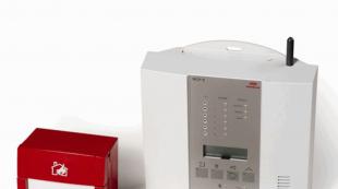
In this article, we will eliminate the most common damage in satellite receiver, namely, we will repair the power supply of this device. Why exactly the power supply? Yes, because in 95% of cases of receiver failure, the culprit is the power supply. may not turn on at all, may turn on “half” (for example: the red indicator is on, and the green, despite our efforts when a certain button is pressed, a lot of signs still don’t turn on), or some function may not work. And the cause of all these misunderstandings, in most cases, may be the power supply. We will repair the “SVEC” receiver, but functionally, on most of these devices, the power supplies differ only in the shape and location of the radio elements. The principle of repairing receivers is almost always the same.
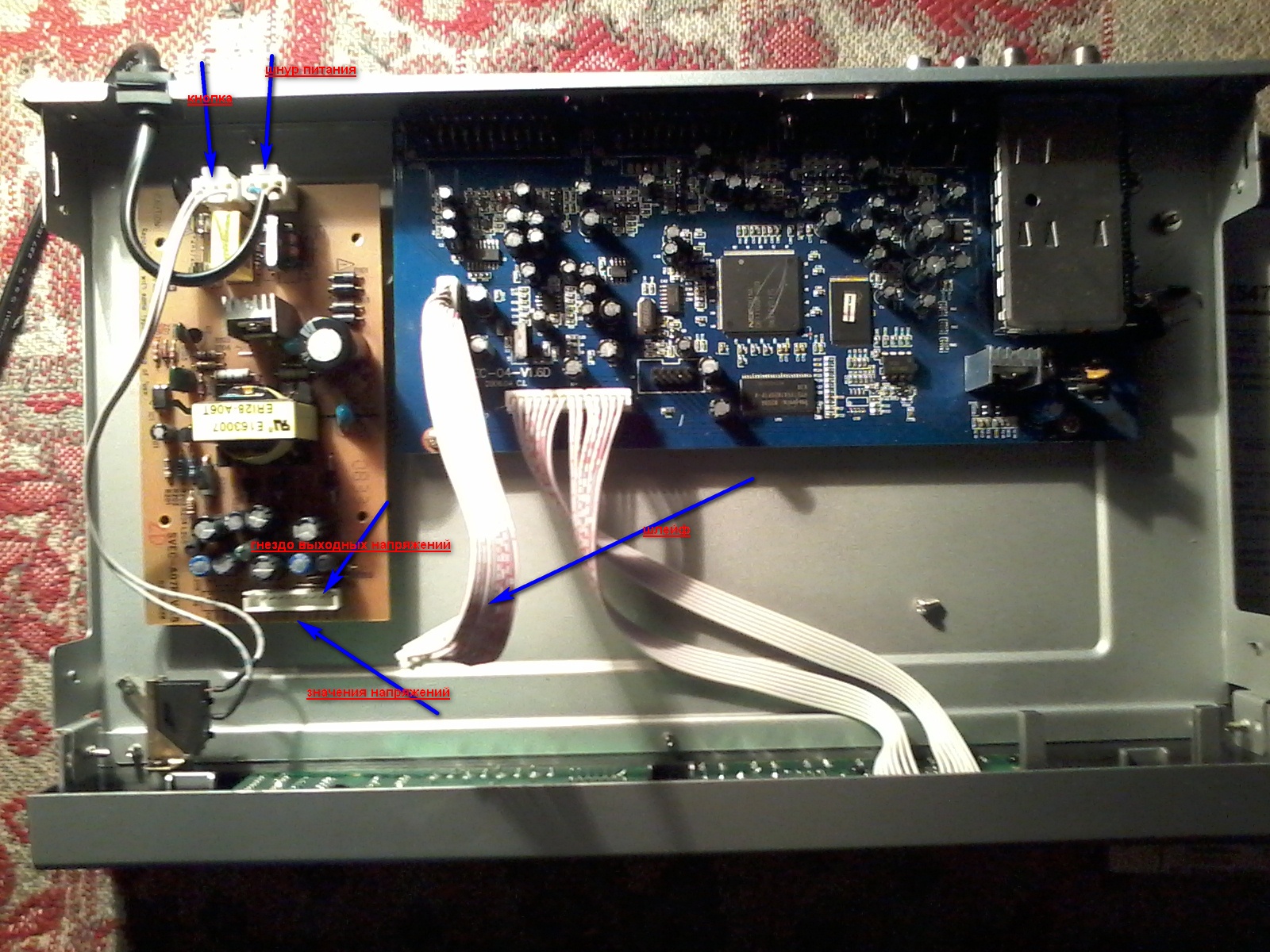
So, let's begin. For starters, of course, you need to disassemble our "unit". Unscrew the screws or bolts on the sides of the lid and remove it. Here we have the following picture:
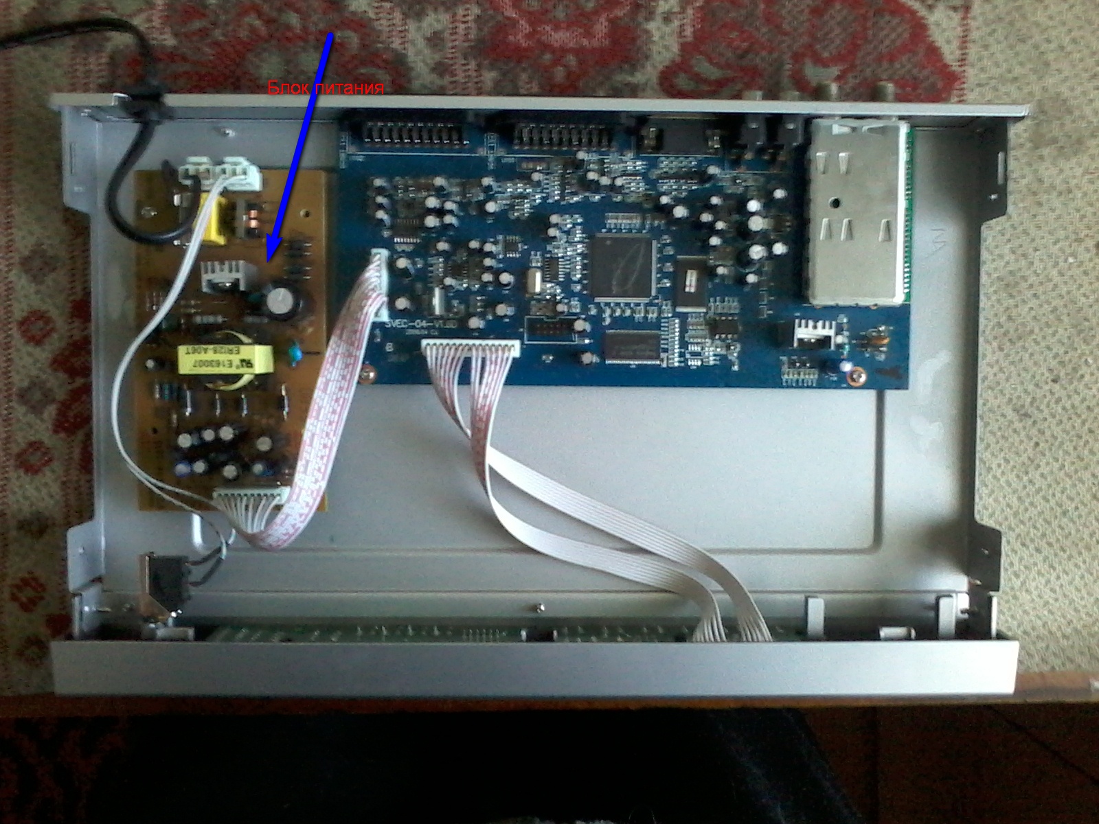
Now let us visually examine the unit and the board for visible reasons for failure (this may be a “bloating” of the capacitors, burnout of the board or individual elements, etc.). If no visible reasons are found, then look at the fuse. Even if you do not visually see that the fuse is “blown”, it’s better to check its integrity with the device. If the fuse is not working, do not rush to change it and try to turn on the receiver. Usually they just don’t “burn out”, on the contrary, for the most part, when overvoltage in the network, they remain unharmed, and something else necessarily fails. This is how modern technology works. In general, we need to remove the power supply (in the figure it is marked with a blue arrow) from the receiver to check other elements.
First of all, you need to check the power capacitor: there may be a residual charge in it. If there is a charge in the capacitor, it is necessary to discharge it, otherwise when checking other radio elements, we can not only “burn” the device, but also get a good electric shock, even if it is not fatal, but still unpleasant.
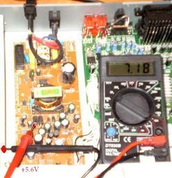
After that, we proceed to check the main transistor, which is on the radiator. If we discard all professional terms, then we simply “ring” it for a “short circuit”. These transistors are constantly failing, designated like this: D13009K. Literal values \u200b\u200bcan be different, and numeric values \u200b\u200bmust match. This transistor is in many receivers, but not in all. Others are similar or may have microcircuits. This is not the point, it is important that in most cases, it is power transistors or microcircuits that fail.
On our power supply, after checking this transistor, a short circuit was detected between its contacts. From this it follows that the transistor is “burnt out”.
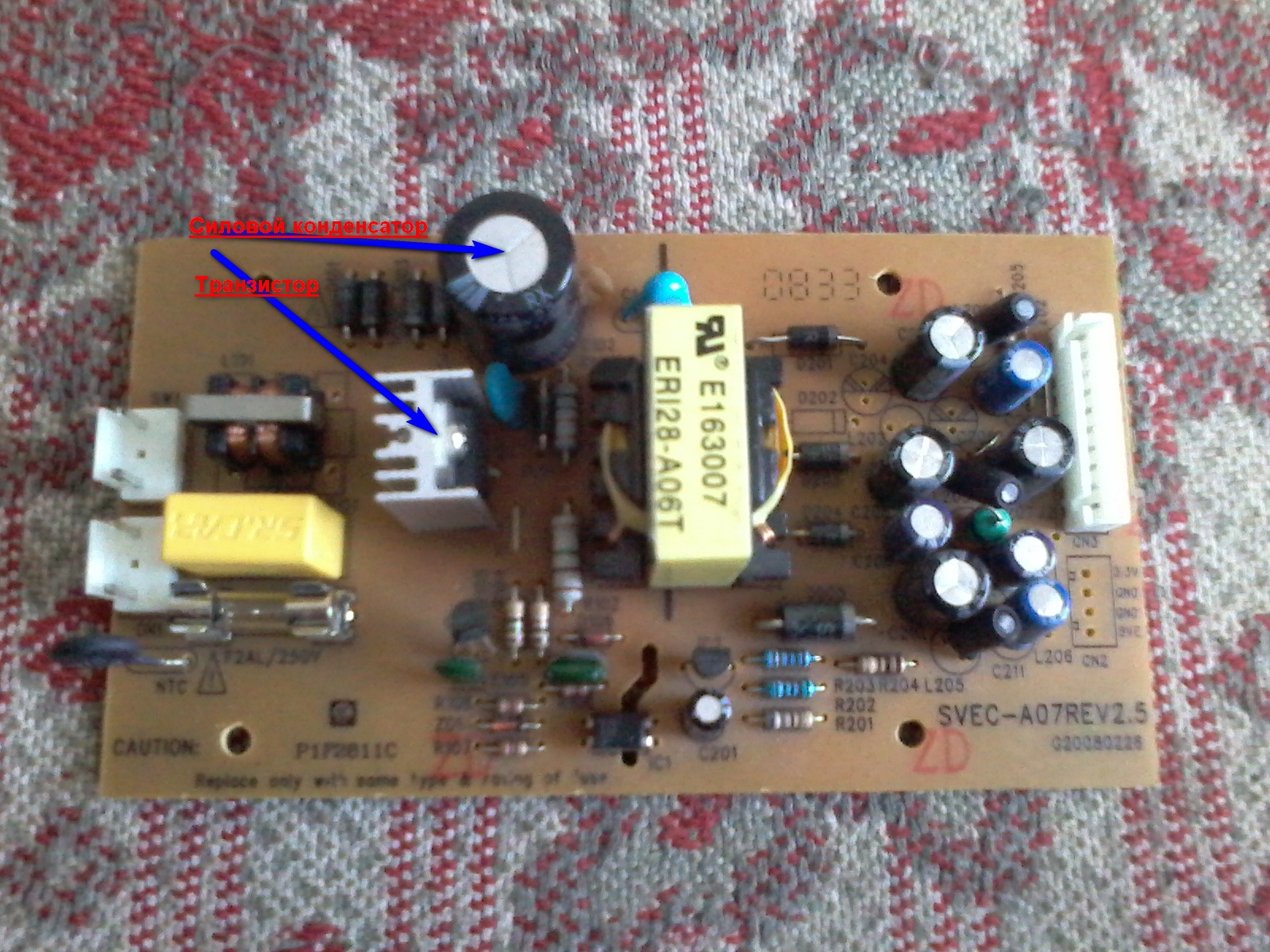
Now we need to solder it and check the rest of the radio elements. I will explain the test in a simple way: you need to check all transistors and diodes (zener diodes) for a "short circuit".
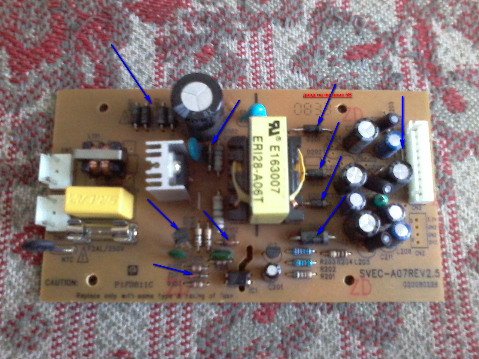
All parts marked with arrows in the picture must be checked for a “short circuit”. After such a check, I found a “burned out” diode, which is powered by 5V. We also need to solder it, so that, like the transistor, replace with a suitable one.
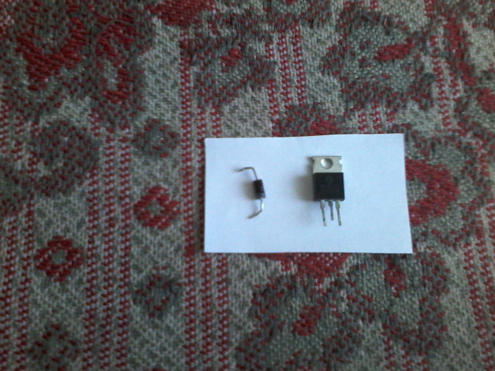
Next, solder the new transistor and diode into place. After that, you can check our power supply. We do it this way: insert it into the receiver and connect only the power cord and the power button to it. A cable with wires that goes to a board with processors is NOT connected. We will check by the output voltages, the value of which is indicated on the power supply, near the "socket" where the loop is inserted.
We measure the voltage at the output of the power supply and, if they match the values \u200b\u200bon the board, you can connect a loop.
All. Now we fasten all the bolts that attach the power supply to the receiver and close our device with a lid. Done.
That, in general, is all. Our receiver works again, like new.
Of course, the most common and not complicated type of damage is described here. There may be more serious reasons for the failure of this device. Then, without the intervention of a specialist, it is impossible to do, but without doing anything, it is impossible to learn anything.
During operation satellite receivers Globo, Bigsat, Allsat, Yumatu, Lumax, Digital, Boston and others like them, one malfunction inherent in all of them was noticed:
The tuner does not start, the LED on the front panel lights up, and the digital display does not light up or flickers weakly. The reason for this behavior of the tuners was a malfunction of the power supplies on the + 3.3V circuits, much less often on the + 5V circuits.
More than 90% of the reasons were substandard power supply capacitors (C15) in chains of 3.3 volts.
It is important to remember that the stabilization of the voltage group of the entire power supply unit is carried out precisely through the + 3.3V circuit, and it is in it that the optocoupler LED (PC817) is installed.
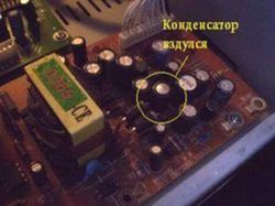
Defective capacitors often swell, and their end surface takes a spherical shape. You can identify a swollen capacitor visually.
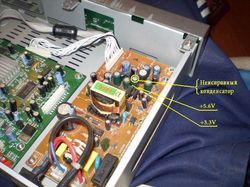
At the initial stage of drying the capacitor (C15), the voltage + 3.3V is normal (feedback can still compensate for the decrease in the capacitance of the capacitor), (but the remaining voltages will be higher than normal). The voltages in the + 5V, + 12V and + 22V circuits (for faults in the + 3.3V circuit) will be overstated. (The stabilization circuit seeks to maintain the voltage in the circuit + 3.3V normal, while simultaneously increasing the voltage in all secondary voltage circuits)
After replacing faulty elements, all voltages return to normal both at idle and under load.
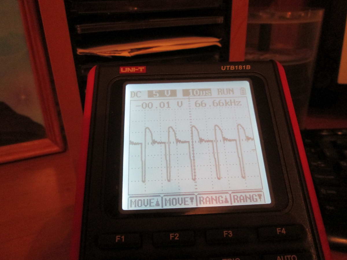 voltage to diode D8
 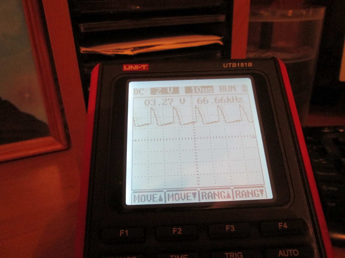 voltage after diode D8
 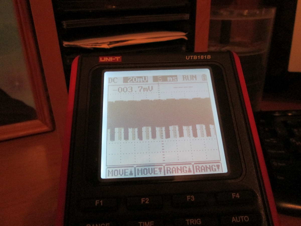 tr voltage
On the waveform "voltage after the diode D8" (there should be a straight horizontal line at the level of +3.3 V);
Replacing faulty containers is usually enough to restore the tuner. Motherboards of this type of equipment have a fairly high reliability.
Note: Once, in addition to replacing the capacitors, the rectifier diode (D8) in the +3.3 V circuit was required to be replaced. In some tuner models, the power supply circuit has a different numbering of elements.
In some cases, due to overvoltage in the network, 2 diodes in the bridge on the high voltage side and a fuse burned out. Diodes burn in pairs. Burnt diodes are short-circuited, so they only pull a fuse with them, the rest of the circuit usually remains intact.
The circuit of the power supply on the dmo265r chip (can be increased by clicking on the picture)
satellite tuners Globo, Boston, BigSAT ...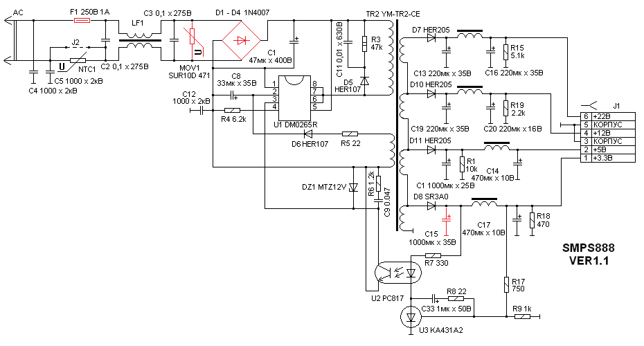
- F1 - fuse;
- C4, C5 - capacitive voltage divider provides half the voltage of the network on the device body (implemented in almost all AV equipment for the possibility of safe connection of the equipment);
- C2, LP1, C3 - prevent the penetration of RF debris from the UPS into the network;
- NTC-1 - thermistor, acts as a limiter of the capacitor charge current, at the time of connecting the UPS to the network;
- MOV1 - a varistor (210pF 470volts 10%) limits the effect of surge surges on the UPS (during prolonged surges, they close and burn a fuse, protecting the rest of the circuit);
- D1, D2, D3, D4 - diode bridge, mains voltage rectifier ;;
- C1 - smoothes the ripple of the rectified network voltage (the voltage on it is about 310 V);
- C11, R3, D5 - the chain limits the bursts of the EMF of the primary winding of the transformer at the moment of closing the power transistor (protects the power transistor of the microcircuit)
- U1 - a microcircuit, includes a control circuit and a power transistor;
- R5, D6, C8 - power the microcircuit after starting (turning on) from the additional winding of the transformer;
- R4 - current limiter;
- C12 -
- DZ1 - Zener diode (not recommended in the circuit recommended by the manufacturer)
- C9, R61 - filter in the circuit of the stabilization circuit;
- U2 - optocoupler;
- TR2 - transformer;
- D7 - rectifier diode in the circuit +22 V;
- C13, L1, C16 - filter in the circuit in the circuit +22 V;
- D10 - rectifier diode in the +12 V circuit;
- C19, L4, C20 - filter in the +12 V circuit;
- D11 - rectifier diode in the +5 V circuit;
- C1, L3, C14 - filter in the +5 V circuit;
- D8 - rectifier diode in the circuit +3.3 V;
- C15, L2, C17 - filter in the circuit +3.3 V;
- R15, R19, R1, R18 - load resistors (provide voltage stability with a significant reduction in load in the circuit);
- R17, R9 - voltage divider (normal mode provides voltage division of 3.3 V / 2.5 V);
- U2, U3 - KA431A2 chip. In the normal state, at the input 2 2.5 V. With an increase in voltage in the circuit +3.3 V, the voltage at input 2 of the KA431A2 chip also increases. In this case, the output transistor opens and the optocoupler U3 LED (PC817) lights up;
- R7 - The limiting resistance provides a normal mode for the LED optocoupler PC817;
- C33, R8 - the chain excludes self-excitation of the KA431A2 chip.
The microcircuit is powered as follows:
- - when the supply voltage (310 V) appears on capacitor C1 and terminal 5 of the microcircuit through an internal current limiting circuit, an internal key, terminal 2 of the microcircuit charges capacitor C8 to a voltage of 12 V. Next, the key breaks the described circuit;
- - the PWM generator starts and the circuit is powered by the circuit: additional transformer winding, R5, D6, capacitor C8.
The power supply circuit on the chip STRG6351 (can be increased by clicking on the picture)
- F81 - fuse;
- C81, C82, L81 - prevent the penetration of RF debris from the UPS into the network;
- C83, C84 - a capacitive voltage divider provides half the mains voltage on the device case (110 V with respect to zero and 110 V with respect to phase. It is implemented in almost all AV equipment for the possibility of safe connection of equipment powered from one outlet);
- RU81 - the varistor limits the influence of the surge voltage of the network on the UPS (during prolonged overvoltages, the fuse closes and burns, protecting the rest of the circuit);
- D81, D82, D83, D84 - diode bridge, mains voltage rectifier;
- MCT 100-9 - breaking resistance, acts as a limiter of the charge current of the capacitor C85, at the time of connecting the UPS to the network. Burns down when the microcircuit STRG6351 is damaged;
- C85 - smooths the ripple of the rectified network voltage (the voltage on it is about 310 V);
- C86, D85, R82 - the chain limits the bursts of the EMF of the transformer primary winding at the moment of closing the power transistor (protects the power transistor of the STRG6351 chip);
- R81, C87 - provide a supply voltage to the control circuit of the STRG6351 chip at the time of startup (on);
- IC81 - the STRG6351 chip (converter) includes a control circuit and a power transistor;
- R83, D86, C87 - power the control circuit of the STRG6351 chip after starting (turning on) from the additional winding of the transformer;
- R86, PC81, \u200b\u200bD87, C88– part of the stabilization circuit located on the high-voltage side of the UPS. When the optocoupler LED is ignited, the phototransistor opens, the voltage on the capacitor C88 and the 6th output of the STRG6351 chip increases, which leads to a decrease in the duration of the open state of the power transistor and lower output voltages;
- R85, R84, C88 - overload protection circuit. When overloaded, the current in the circuit increases: the primary winding of the transformer, power transistor, resistance R84\u003e the voltage at C88 and terminal 6 of the STRG63511 chip increases, which leads to a decrease in the open state of the power transistor;
- D26, C30 - rectifier circuit +30 V;
- L26, C31 - +30 V circuit filter;
- D25, C28 - rectifier circuit +23 V;
- L25, C29 - +23 V circuit filter;
- D23, C25 - rectifier circuit +12 V;
- IC21, C26 - +12 V circuit stabilizer;
- D22, C23 - rectifier circuit +7 V;
- L22, C24 - filter circuit +7 V;
- D21, C21 - a rectifier circuit +3.3 V;
- L21, C22 - circuit filter +3.3 V;
- R31, R27, R22, R21 - load resistors (provide voltage stability with a significant reduction in load in the circuit);
- R53, R54 - voltage divider (normal mode provides voltage division of 3.3 V / 2.5 V);
- IC51, C51 - TL431 chip. In the normal state, at the input 2 2.5 V. With an increase in the voltage in the circuit +3.3 V, the voltage at the input 2 of the TL431 chip also increases. In this case, the output transistor opens and the PC81 optocoupler LED lights up;
- R51, PC81 - The limiting resistance provides normal operation for the PC817 LED.
Part of the stabilization circuit located on the low voltage side of the UPS.
If the information found was useful
You can help the project
I'm index Money:
Having transferred any amount to QIWI Wallet +375291370623
Having transferred any amount to the wallet WebMoney
Z413349611842 Dollars
E582325801050 Euro
R334502019215 Ruble
U404807543728 Hryvnia
the tuner does not start, the LED on the front panel lights up, and the digital display does not light up or flickers weakly. The selection, acquisition and installation of a satellite TV system (SAT TV) is not an overwhelming task. No special devices are needed to tune the antenna to the satellite (by the way, the vast majority of numerous installers of satellite systems do not have them). This article will help you do it yourself.
In order to orient the antenna (dish) in the area, you should use the site: www.dishpointer.com Go to the site, indicate your location, choose a satellite. You will receive a map of your area of \u200b\u200bthe city and the direction to the satellite.
Voltage Regulator Test Scheme:MOTOROLA 9RC2054
MOBILETRON VR-VW010
TRANSPO M511
HUCO 13 0696
Ger04 The VALEO SG15L027 155A generator is installed on RENAULT SCENIC 2 cars with a 1.9 dci engine of 120 hp. F9Q
A water-cooled generator is used to heat the windshield with heating elements
During operation of the car Renault Scenic-2 the motor stopped working, unlocking the mechanism for moving the armrest box. How to charge a car battery with a laptop power supply.Power Supply Parameters Uout 18.5 V Iout 3.5 A
Found a low beam lamp 12 V 55 W to limit the charge current.
Connected in series:
+ PSU output
+ lamps
- lamps