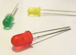
The image on the diagram of a two-color LED. Two-color and three-color LEDs
Once they asked me to make a lamp that could change colors, because one-color can quickly become boring: in short, something like a night lamp. Of course, the backlighting method described in this article is also suitable for interior lighting of a computer, therefore this article can be interesting both from the point of view of design ideas and for fans of modding.
I somehow did not want to do the usual three-color lamp on the toggle switches and three LEDs, because it is much more interesting when the number of colors is not limited by the number of LEDs.
Necessary materials:
- A tri-color superbright RGB LED with a diameter of 8 mm with a brightness like that is 4000 mcd (or 3 superbright LEDs with a diameter of 3-5 mm: blue, green, red).
- Variable resistors 0 - 1.5 kOhm with load switching off - 3 pcs.
- Four wire
- Plexiglas cube 30x30x30 mm
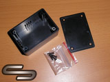
- Housing for radio devices
- 3 adjustment knobs
- Plastic bottle cap (or magnet from PC speaker)
- Regulated power supply (if you are going to power this device from a computer, take either a USB cable or a power splitter (molex))
- Shrink or insulating cambric
- Black electrical tape
Instruments:
- Engraver (aka Dremel) - in principle, you can do without him
- Glue gun
- File Set
- Drill
- Needle files
- Sandpaper
- Pliers
- Side cutters
- Gun knife
- Lighter
- A bit of fantasy
So let's get started.
First, consider a three-color LED. He has 4 conclusions: general (+) and 3 legs, responsible for color. Connecting a minus to one of the legs, the LED will glow either blue, or green, or red. It looks like this:
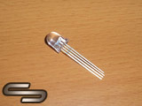
If you look closely, you can see that one of the legs inside the LED housing has a T-shape - this is the common (+). In the photo, the legs are from left to right: red (-), general (+), blue (-), green (-). If you did not find a three-color LED on sale, then you can replace it with three one-color ones, soldering their plus legs together.
In fact, the desired color of the lamp can be achieved by changing the brightness of each of the three colors of the LED, which will shine simultaneously from under one lampshade and, merging into one color, will give the one we need.
The brightness adjustment will be performed by variable resistors, each of which will be connected in series with the legs of the color of the LED.
The variable resistor has 3 pins:
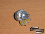
The central leg is a general conclusion. Rotating the knob clockwise, the resistance between the first leg and the second (central leg) will increase, and between the second and third - will decrease. It is most convenient to use the second and third leg - so rotating the knob clockwise, the brightness of the color to which this resistor will be connected will increase.
Since I decided to make the color control unit remote, I had to buy a housing for radio devices. Its size should be such that it is enough to accommodate 3 variable resistors. For example, the diameter of the round part of my resistors was 15 mm, so a small case was chosen. Low-power resistors are small, just such will be enough. The case is a plastic box with a lid, which is mounted on self-tapping screws:
First you need to choose the location of the handles and decide which side the wire will go into the color control unit, and which side to exit. Then we mark the centers of the holes (making this very convenient with an awl). Before drilling, you need to tilt the marking. This can be done with a drill with a diameter of 3 mm, a couple of times scrolling it manually. Now we drill holes under the wire with a drill at low speeds. If you drill on large - the plastic will melt and it will have to be removed. The size of the hole will naturally depend on the diameter of the wires.
Before drilling holes for the adjustment knobs, we determine the method of mounting variable resistors. One way is to mount it on a printed circuit board and then fasten it with brackets to the inner walls of the case. In this case, the handles are deepened into the body, respectively, the holes are made under them. The handles I used look like this:
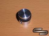
If you do mounted mounting, then you can just drill holes in the housing for mounting variable resistors, which I actually did. For example, it’s just more convenient for me if the handle is fully open. When all the holes have been drilled, we remove the burrs with needle files.
Regarding the power source - here you can take, for example, an adjustable power supply from 1.5 to 12 V in increments of 1.5 V.

The voltage must be set corresponding to the LED. Usually such LEDs are 3 V, so there is no need to install an additional resistor. Personally, I chose charging from the Motorola C350 as the power source and put a 150 Ohm resistor on each negative leg of the diode.
If you connect our device to a computer, then it can be powered either from a power splitter (molex), or from a USB cable.
![]()
For those who do not know, the red wire in the molex is +5 V, the black wire is the earth. Or take the USB cable and cut off the unnecessary plug, leaving only the USB output. Strip it. There will be 4 wires: black (earth), red (+5 V), green and white (be sure to insulate them: they will not be useful to us). Since the power is 5 V, and the LED is 3 V, we put a resistor on each leg of the color of the LED. In this case, it is 150 Ohms (it is better to take a little with a margin).
Everyone is familiar with LEDs now. Without them, modern technology is simply unthinkable. These are LED lights and lamps, an indication of the operating modes of various household appliances, the illumination of screens of computer monitors, televisions, and many other things that you can’t even remember right away. All of these devices contain LEDs in the visible radiation range of various colors: red, green, blue (RGB), yellow, white. Modern technology allows you to get almost any color.
In addition to the LEDs in the visible range, there are infrared and ultraviolet LEDs. The main field of application of such LEDs is automation and control devices. Enough to remember. If the first remote control models were used exclusively for controlling TVs, now they can be used to control wall heaters, air conditioners, fans, and even kitchen appliances, such as crock pots and bread machines.
So what is an LED?
In fact, it is not much different from the usual one - all the same p-n junction, and all the same basic property of one-sided conductivity. As we studied the p-n junction, it turned out that in addition to one-sided conductivity, this very junction also has several additional properties. In the process of evolution of semiconductor technology, these properties have been studied, developed and improved.
A great contribution to the development of semiconductors was made by the Soviet radio physicist (1903 - 1942). In 1919 he entered the famous and still well-known Nizhny Novgorod radio laboratory, and since 1929 he worked at the Leningrad Physical-Technical Institute. One of the activities of the scientist was the study of a weak, slightly noticeable, glow of semiconductor crystals. It is on this effect that all modern LEDs work.
This weak luminescence occurs when the current is passed through the pn junction in the forward direction. But at present, this phenomenon has been studied and improved so much that the brightness of some LEDs is such that it can simply be blinded.
 The color scheme of LEDs is very wide, almost all the colors of the rainbow. But the color is not obtained at all by changing the color of the LED housing. This is achieved by the fact that dopants are added to the pn junction. For example, the introduction of a small amount of phosphorus or aluminum allows you to get the colors of red and yellow, and gallium and indium emit light from green to blue. The LED housing can be transparent or matte, if the housing is colored, then it is just a color filter that matches the color glow p-n transition.
Another way to obtain the desired color is the introduction of a phosphor. Phosphor is a substance that gives visible light when exposed to it by other radiation, even infrared. A classic example is fluorescent lamps. In the case of LEDs, white is obtained by adding a phosphor to the crystal of blue glow.
To increase the radiation intensity, almost all LEDs have a focusing lens. Often, the end face of a transparent body having a spherical shape is used as a lens. In infrared light emitting diodes, sometimes the lens appears to be opaque, smoky gray. Although in recent years, infrared LEDs are available simply in a transparent case, these are the ones used in various remote controls.

Bi-color LEDs
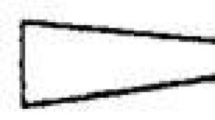
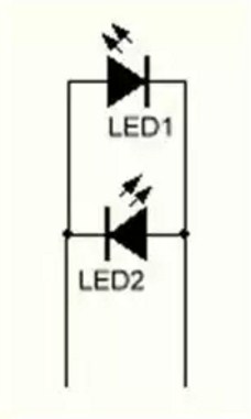
Also known to almost everyone. For example, a charger for a mobile phone: while charging, the indicator lights up in red, and at the end of charging it turns green. Such an indication is possible due to the existence of two-color LEDs, which can be of different types. The first type is three-output LEDs. One housing contains two LEDs, for example, green and red, as shown in Figure 1.
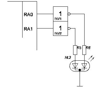
Figure 1. Connection diagram of a two-color LED
The figure shows a fragment of a circuit with a two-color LED. In this case, a three-output LED with a common cathode is shown (there are also with a common anode) and its connection to. In this case, you can turn on either one or the other LED, or both at once. For example, it will be red or green, and when you turn on two LEDs at once, it turns yellow. If at the same time using the PWM modulation to adjust the brightness of each LED, you can get several intermediate shades.
In this circuit, you should pay attention to the fact that the limiting resistors are included separately for each LED, although it would seem that you can do just one by including it in the general output. But with this inclusion, the brightness of the LEDs will change when one or two LEDs are turned on.
What voltage is needed for the LED? Such a question can be heard quite often, it is asked by those who are not familiar with the specifics of the LED or just people very far from electricity. In this case, it is necessary to explain that the LED is a device controlled by current, and not by voltage. You can turn on the LED at least 220V, but the current through it should not exceed the maximum permissible. This is achieved by turning on the ballast resistor in series with the LED.
But still, remembering the voltage, it should be noted that it also plays a big role, because the LEDs have a large forward voltage. If for a conventional silicon diode this voltage is on the order of 0.6 ... 0.7 V, then for a LED this threshold starts from two volts and above. Therefore, from a voltage of 1.5 V, the LED does not light.
But with this inclusion, we mean 220V, we should not forget that the reverse voltage of the LED is quite small, not more than several tens of volts. Therefore, in order to protect the LED from high reverse voltage, special measures are taken. The easiest way is counter-parallel connection of a protective diode, which may also be not very high voltage, for example, KD521. Under the influence of alternating voltage, the diodes open alternately, thereby protecting each other from high reverse voltage. The protective diode switching circuit is shown in Figure 2.
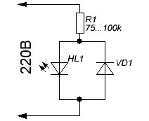
Figure 2 Wiring diagram parallel to the LEDprotective diode
Two-color LEDs are also available in a two-pin package. A change in the color of the glow in this case occurs when the direction of the current changes. A classic example is an indication of the direction of rotation of a DC motor. At the same time, one should not forget that the limiting resistor is necessarily switched on in series with the LED.
Recently, a limiting resistor is simply built into the LED, and then, for example, on the price tags in the store they simply write that this LED is 12V. Also, blinking LEDs are marked by voltage: 3V, 6V, 12V. Inside such LEDs there is a microcontroller (it can even be seen through a transparent case), so any attempts to change the blinking frequency do not give results. With this marking, you can turn on the LED directly to the power supply at the specified voltage.
Developments of Japanese amateur radio
Radio amateur, it turns out, is engaged not only in the countries of the former USSR, but also in such an "electronic country" as Japan. Of course, even a Japanese ordinary amateur radio amateur cannot create very complex devices, but individual circuitry solutions deserve attention. You never know in which scheme these solutions can come in handy.
Here is an overview of relatively simple devices that use LEDs. In most cases, control is carried out from microcontrollers, and you can’t get anywhere. Even for a simple circuit, it’s easier to write a short program and solder the controller in the DIP-8 package than to solder several microcircuits, capacitors and transistors. It is also attractive that some microcontrollers can work without any attached parts.
Two-color LED control circuit
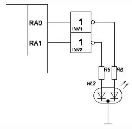
An interesting scheme for controlling a powerful two-color LED is offered by Japanese hams. More precisely, two powerful LEDs with a current of up to 1A are used here. But, it must be assumed that there are powerful two-color LEDs. The diagram is shown in Figure 3.
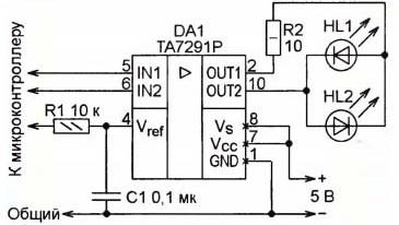
Figure 3. Powerful two-color LED control circuit
Chip TA7291P is designed to control DC motors of small power. It provides several modes, namely: rotation forward, backward, stop and braking. The output stage of the microcircuit is assembled according to the bridge circuit, which allows you to perform all of the above operations. But it was worth making some imagination and now, please, the microcircuit has a new profession.
The logic of the chip is quite simple. As can be seen in Figure 3, the microcircuit has 2 inputs (IN1, IN2) and two outputs (OUT1, OUT2), to which two powerful LEDs are connected. When the logic levels at inputs 1 and 2 are the same (no matter 00 or 11), then the potentials of the outputs are equal, both LEDs are off.
At different logical levels at the inputs, the microcircuit works as follows. If one of the inputs, for example, IN1 has a low logic level, then the output OUT1 is connected to a common wire. The cathode of the HL2 LED through the resistor R2 is also connected to a common wire. The voltage at the output OUT2 (if there is a logical unit at the input IN2) in this case depends on the voltage at the input V_ref, which allows you to adjust the brightness of the LED HL2.
In this case, the voltage V_ref is obtained from the PWM pulses from the microcontroller using the integrating chain R1C1, which controls the brightness of the LED connected to the output. The microcontroller also controls the inputs IN1 and IN2, which allows you to get a wide variety of shades of light and algorithms for controlling LEDs. The resistance of the resistor R2 is calculated based on the maximum permissible current of the LEDs. How to do this will be described below.
Figure 4 shows the internal structure of the TA7291P chip, its structural diagram. The circuit is taken directly from the datasheet, therefore, an electric motor is depicted as a load on it.
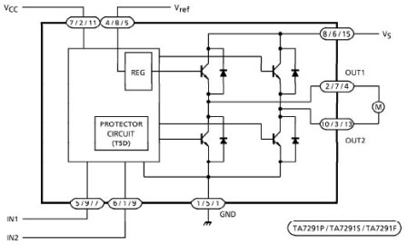
Figure 4
According to the structural scheme, it is easy to trace the current paths through the load and the methods for controlling the output transistors. Transistors are turned on in pairs, diagonally: (upper left + lower right) or (upper right + lower left), which allows you to change the direction and frequency of rotation of the motor. In our case, light one of the LEDs and control its brightness.
The lower transistors are controlled by the signals IN1, IN2 and are designed simply to turn on / off the diagonals of the bridge. The upper transistors are controlled by the Vref signal, they regulate the output current. The control circuit, shown simply by a square, also contains a short circuit protection circuit and other unforeseen circumstances.
Ohm's law will always help in these calculations. The initial data for the calculation let them be as follows: the supply voltage (U) is 12V, the current through the LED (I_HL) is 10mA, the LED is connected to a voltage source without any transistors and microcircuits as an inclusion indicator. Voltage drop on the LED (U_HL) 2V.
Then it is quite obvious that the voltage (U-U_HL) will be necessary for the limiting resistor, - the LED itself “ate” two volts. Then the resistance of the limiting resistor is
R_o \u003d (U-U_HL) / I_HL \u003d (12 - 2) / 0.010 \u003d 1000 (Ω) or 1KΩ.
Do not forget about the SI system: voltage in volts, current in amperes, the result in Ohms. If the LED is turned on by the transistor, then in the first bracket, the voltage of the collector - emitter section of the open transistor should be subtracted from the supply voltage. But this, as a rule, no one ever does, accuracy to hundredths of a percent is not needed here, and it won’t work out due to the spread of details of the parts. All calculations in electronic circuits give approximate results, the rest has to be achieved by debugging and tuning.
Tri-color LEDs
In addition to two-color lately, tri-color (RGB) LEDs have become widespread. Their main purpose is decorative lighting on stages, at parties, at New Year's celebrations or at discos. Such LEDs have a housing with four leads, one of which is a common anode or cathode, depending on the specific model.
But one or two LEDs, even three-color ones, are of little use, so you have to combine them into garlands, and to control garlands use all kinds of control devices, which are most often called controllers.
Assembling garlands of individual LEDs is boring and uninteresting. Therefore, in recent years, the industry began to produce, as well as tapes based on tri-color (RGB) LEDs. If single-color tapes are produced at a voltage of 12V, then the operating voltage of three-color tapes is often 24V.
LED strips are marked by voltage, since they already contain limit resistors, so they can be connected directly to a voltage source. Sources for sale in the same place as the tape.
To control three-color LEDs and ribbons, to create various lighting effects, special controllers are used. With their help, it is possible to easily switch the LEDs, adjust the brightness, create various dynamic effects, as well as draw patterns and even paintings. The creation of such controllers attracts many hams, naturally those who can write programs for microcontrollers.
Using a three-color LED, you can get almost any color, because the color on the TV screen is also obtained by mixing only three colors. Here it is appropriate to recall another development of Japanese amateur radio. Her circuit diagram shown in figure 5.
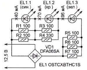
Figure 5. Connection diagram of a three-color LED
Powerful 1W three-color LED contains three emitters. With the resistors indicated on the diagram, the color of the glow is white. By selecting the resistor values, a slight change in shade is possible: from white cold to white warm. In the author's design, the lamp is designed to illuminate the interior of the car. Will they (the Japanese) be sad! In order not to worry about observing the polarity, a diode bridge is provided at the input of the device. The device is mounted on a breadboard and shown in Figure 6.
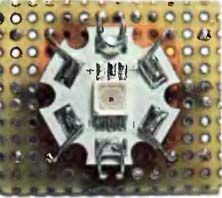
Figure 6. Development board
The next development of Japanese radio amateurs is also automotive. This device for illuminating the room, of course, on white LEDs is shown in Figure 7.
Figure 7. Scheme of the device for highlighting the numbers on white LEDs
The design used 6 high-power ultra-bright LEDs with a limiting current of 35 mA and a luminous flux of 4 lm. To increase the reliability of the LEDs, the current through them is limited to 27 mA using a voltage regulator chip included in the current stabilizer circuit.
LEDs EL1 ... EL3, resistor R1 together with the DA1 chip form a current stabilizer. A stable current through the resistor R1, supports a voltage drop of 1.25V on it. The second group of LEDs is connected to the stabilizer through exactly the same resistor R2, so the current through the group of LEDs EL4 ... EL6 will also be stabilized at the same level.
Figure 8 shows a converter circuit for powering a white LED from a single 1.5V cell, which is clearly not enough to light an LED. The converter circuit is very simple and controlled by a microcontroller. In fact, the microcontroller is a pulse frequency of about 40KHz. To increase the load capacity, the outputs of the microcontroller are paired in parallel.
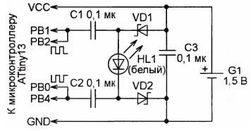
Figure 8
The scheme works as follows. When the outputs PB1, PB2 are low, the outputs PB0, PB4 are high. At this time, capacitors C1, C2 are charged through the diodes VD1, VD2 to about 1.4V. When the status of the controller outputs is reversed, the sum of the voltages of two charged capacitors plus the voltage of the battery will be applied to the LED. Thus, almost 4.5V will be applied to the LED in the forward direction, which is enough to ignite the LED.
A similar converter can be assembled without a microcontroller, just on a logic chip. Such a circuit is shown in Figure 9.
Figure 9
On the element DD1.1 assembled a generator of square waves, the frequency of which is determined by the ratings R1, C1. It is with this frequency that the LED will flash.
When the output element is DD1.1 high level output DD1.2 naturally high. At this time, the capacitor C2 is charged through the diode VD1 from the power source. The charge path is as follows: plus the power source - DD1.1 - C2 - VD1 - DD1.2 - minus the power source. At this time, only the battery voltage is applied to the white LED, which is not enough to light the LED.
When the level becomes low at the output of the DD1.1 element, a high level appears at the output of DD1.2, which leads to the blocking of the diode VD1. Therefore, the voltage across capacitor C2 is added to the voltage of the battery and this sum is applied to resistor R1 and LED HL1. This sum of voltages is enough to turn on the HL1 LED. Next, the cycle repeats.
How to check the LED
If the LED is new, then everything is simple: the conclusion that is slightly longer is the plus or the anode. It is it that must be included in the plus of the power supply, naturally not forgetting about the limiting resistor. But in some cases, for example, the LED was pulled out of the old board and the conclusions are the same length, a call is required.
Multimeters in this situation behave somewhat incomprehensibly. For example, a DT838 multimeter in the semiconductor test mode may simply slightly illuminate the LED under test, but at the same time an open circuit is shown on the indicator.
Therefore, in some cases, it is better to check the LEDs by connecting them through the limiting resistor to the power source, as shown in Figure 10. The resistor value is 200 ... 500 Ohm.
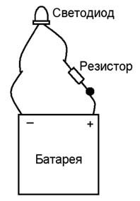
Figure 10. LED test circuit
Figure 11. Sequential inclusion of LEDs
It is not difficult to calculate the resistance of the limiting resistor. To do this, add the direct voltage to all the LEDs, subtract it from the voltage of the power source, and divide the resulting residue by the given current.
R \u003d (U - (U_HL_1 + U_HL_2 + U_HL_3)) / I
Suppose that the voltage of the power supply is 12V, and the voltage drop at the LEDs is 2V, 2.5V and 1.8V. Even if the LEDs are taken from one box, there can still be such a spread!
By condition of the task, a current of 20 mA is set. It remains to substitute all the values \u200b\u200bin the formula and teach the answer.
R \u003d (12- (2 + 2.5 + 1.8)) / 0.02 \u003d 285Ω
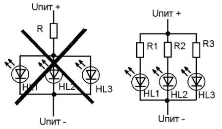
Figure 12. Parallel activation of LEDs
On the left fragment, all three LEDs are connected through one current-limiting resistor. But why is this scheme crossed out, what are its drawbacks?
It affects the spread of the LEDs. The greatest current will go through the LED, in which the voltage drop is less, that is, the internal resistance is less. Therefore, with this inclusion, it will not be possible to achieve a uniform glow of the LEDs. Therefore, the scheme shown in Figure 12 on the right should be recognized as the correct circuit.
Each LED has its own glow color. It depends on the material of the semiconductor and does not change during the operation of the device. To make multi-color LEDs, it is necessary to assemble several crystals emitting different colors together.
How does a two-color LED work?
The name two-color LED did not come from the fact that the device is somehow painted in a special way, but because it can glow in two colors. They are included separately. For example, if we are talking about a red-green lamp, at first only red lights up, then red goes out and green lights up. This feature is associated with the device.
All two-color LEDs are made with two pins. Color changes depending on which direction current flows through the lamp. The scheme of such a device is quite understandable. It contains a resistor and two diodes connected to each other. Diodes are connected in parallel. When the current flows in the forward direction, one diode is turned off and does not glow. In the opposite direction of the current, everything repeats exactly the opposite.
The set of pure colors for LEDs is limited. With great effort, scientists were able to create crystals that generate colors similar to rainbow colors. There is:
- red;
- orange (amber);
- yellow;
- green;
- blue
And how many shades. White, like millions of other tones, is obtained as a result of their combination.
The principle of operation of the three-color LED
For tri-color LEDs, a slightly different scheme is provided. It has a common cathode and two anode terminals. In it, you can turn on two LEDs at once. In this case, both red and green light will be able to burn at the same time, and we will see their result of joint work - yellow.
Using a pulse modulator (special device), the intensity of the glow is changed, and the color tone of the LED changes from this. To prevent overloads, a separate resistor is installed on each diode.
The three-color scheme is more in demand than the two-color scheme, and this is understandable. If you have the same set of sources, significantly more possibilities arise. Such a scheme allows you to assemble inexpensive fixtures that change light in a wide range.
Even more tones, including white light, are obtained when assembling circuits with three multi-colored LEDs. This is famous RGB circuit with a common anode. Outwardly, a three-color lamp is immediately recognized by the presence of four conclusions, in addition, it must be affixed with the corresponding marking.
Theoretically, you can combine many crystals in one housing or on one board and get multi-colored bright LEDs. But in practice, one of the above three-color schemes is used.
Application
Despite their not-so-wide emission spectrum, two-color LEDs find their own niche in instrumentation. They are used for light signaling, in decoration of premises, in advertising. Two-color LEDs are indicators of rotation of a DC-powered engine. They show in which direction the rotation occurs.
Three-color LEDs operating on two crystals find a similar application. Their advantage over three-crystal lamps is their relatively low cost. At the same time, the capabilities of the devices are quite wide.
The operation of such an LED is well illustrated by the indicator light of the charger of our cameras, phones, tablets and many other devices. When the battery is discharged, it glows red, and when fully charged, it glows green.
The name itself - a two-color LED is based on the fact that the chip is able to glow in two colors. A striking example of this type of diode is charging a mobile phone, charging batteries, where the indicator lights up in red during charging, as the battery fills with a charge, the color changes to green.
Two-color LEDs are divided into several types. The most common are three-output LEDs. Two LEDs of green and red glow are integrated in one housing.
 Bi-color LED with two conclusions
 Two-color LEDs have two outputs. A color change occurs depending on which direction the current flows. The two-color LED control circuit is shown below.
 Correct connection of a two-color LED
 The diodes are connected in parallel. When the current flows in one direction, the second diode is locked and does not glow. In the case of reverse current flow, the luminescence occurs on the contrary. When using a PWM controller, both LEDs can be lit at once, as a result of color mixing, yellow or several other shades will be obtained.
Despite the fact that in this circuit we see only two diodes, in some instructions it is commonly called tri-color. Such diodes have three outputs. Such a division is conditional, therefore, attention should not be paid to this.
555 two-color LED control circuit
a residually simple and lightweight dual-color LED control circuit. In this case, the green and red colors turn on alternately.
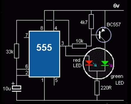 555 Two-color LEDs Control
 control circuit for two-color LEDs up to 1A
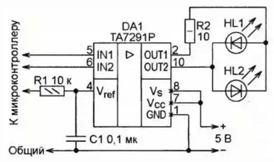 Two-color LED control circuit on the controller
 The two-color LED control circuit is built on the TA7291P chip with two OUT outputs and two IN inputs. We connect two diodes or one two-color power of at least 1A to the output. If the logic at the inputs is the same, then the potentials of the outputs are equal, respectively, the LED does not light.
At different logical levels at the inputs, the microcircuit works as follows. If one of the inputs, for example, IN1 has a low logic level, then the output OUT1 is connected to a common wire. The cathode of the HL2 LED through the resistor R2 is also connected to a common wire. The voltage at the output OUT2 (if there is a logical unit at the input IN2) in this case depends on the voltage at the input V_ref, which allows you to adjust the brightness of the LED HL2.
In this case, the voltage V_ref is obtained from the PWM pulses from the microcontroller using the integrating chain R1C1, which controls the brightness of the LED connected to the output. The microcontroller also controls the inputs IN1 and IN2, which allows you to get a wide variety of shades of light and algorithms for controlling LEDs. The resistance of the resistor R2 is calculated based on the maximum permissible current of the LEDs.
The simplest connection schemes for two-color LEDs
Whatever it is, but I know that working with microcontrollers is scary for many, so I’ll give you a couple of working circuits for controlling a two-color LED without any “bells and whistles”.
The first is a circuit for connecting a two-color diode with two leads:
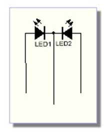
The following diagram for a 2-color LED on three pins:
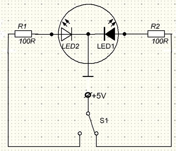 2-Color Three-Pin LEDs Circuit
 The most complete, but for many it will seem complicated, information on two-color LEDs - on this site
Video on the operation of two-color LEDs, simple wiring diagrams
In contact with