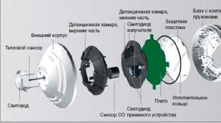
LED glow voltage. LEDs Scheme Description
In modern lighting fixtures, the most advanced light sources known as LEDs are widely used. They are part of signaling, indicator and other devices. However, despite the many positive qualities, the LEDs still periodically fail, and then a problem often arises, how to check the LED with a multimeter.
Why LEDs Fail
Prolonged and correct operation of the LED under ideal conditions is ensured by a strictly normalized current, the indicators of which in no case should exceed the nominal value of the element itself. These parameters can only be achieved using diodes and self-voltage, known as a driver. However, these stabilizing devices are used in conjunction with high power lamps.
Most low-power led bulbs, do not have a driver in the connection chain. To limit the current, a conventional resistor is used that acts as a stabilizer. In practice, this function is far from being fully implemented, which is the main cause of burnout and damage to LEDs. Resistor protection is only possible under ideal conditions, with the correct rated current and a stable supply voltage. However, in reality, these conditions are not fully observed or not at all.
Thus, the burnout of the LEDs occurs due to the low reverse voltage limit characteristic of all elements of this type. Any electrostatic discharge or improper connection is enough for the LED light source to fail. After this, it remains only to check its operability and, if necessary, replace it. It is recommended to check the LEDs before they are mounted on the printed circuit board. This is due to the fact that a certain proportion of products is initially defective due to the fault of the manufacturer.
Using a multimeter to test LEDs
All multimeters belong to the category of universal measuring instruments. Using a multimeter, you can measure the main parameters of any electronic products. In order to check the operability of the LED, you need a multimeter with a dialing mode, which is just used to check the diodes.
Before starting the test, the multimeter switch is set to dialing mode, and the instrument contacts are connected to the tester probes. This verification method allows at the same time solving the question of how to check the LED power with a multimeter, based on the data obtained, it will be easy to calculate this parameter.
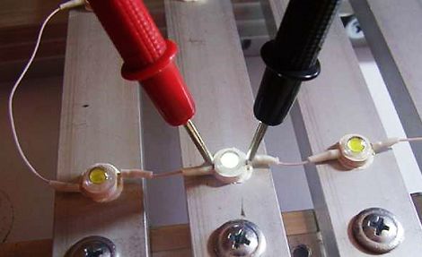
The connection of the multimeter must be carried out taking into account the polarity of the LED. The anode of the element is connected to the red probe, and the cathode is connected to black. If the polarity of the electrodes is unknown, do not be afraid of any consequences as a result of confusion. In case of incorrect connection, the initial parameters of the multimeter will remain unchanged. If the polarity is observed as expected, then the LED should begin to glow.
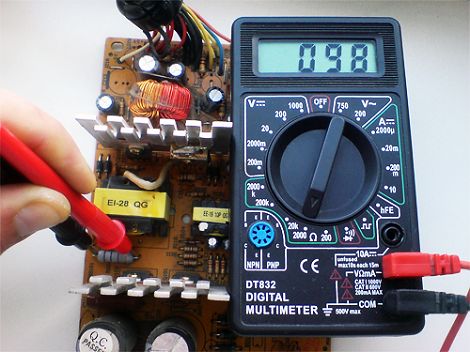
There is one feature that should be considered when checking. in dialing mode it has a fairly low value and the diode may not respond to it. Therefore, in order to clearly see the glow, it is recommended to reduce the external light. If this cannot be done, the readings of the measuring device should be used. During normal operation of the LED, the value displayed on the display of the multimeter will differ from unity.
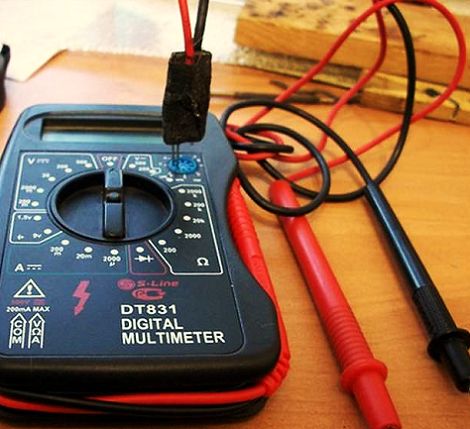
There is another test option with a tester. To do this, the control panel has a PNP unit with which diodes are checked. Its power provides an element luminescence sufficient to determine its operability. The anode is included in the emitter connector (E), and the cathode in the connector block or collector (C). When the measuring device is turned on, the LED should light up regardless of the mode in which the regulator is installed.
The main disadvantage of this method is the need for soldering elements. To solve the problem of how to check the LED with a multimeter without soldering, special adapters will be required for the probes. Conventional probes will not enter the PNP connector, so thinner parts made from paper clips are soldered to the wires. Between them, a small textolite gasket is installed as insulation, after which the entire structure is wrapped with electrical tape. As a result, we have an adapter to which you can connect probes.
After that, the probes are connected to the electrodes of the LED, without evaporating it from the general circuit. In the absence of a multimeter, the test can be performed in the same way using batteries. The same adapter is used, only its wiring is connected not to the probes, but to the battery outputs using small crocodile clips. You will need one 3 volt power supply or two 1.5 volt sources.
If the batteries are new with a full charge, it is recommended to check the yellow and red LEDs with a resistor. It should be 60-70 Ohms, which is quite enough to limit the current. When checking the LEDs in white, blue and green, the current-limiting resistor can be omitted. In addition, a resistor is not required when the battery is very low. To perform its direct functions, it is no longer suitable, and to check the LEDs it will be quite enough.
When disassembling old or inoperative devices for details, you can often find LEDs. However, in most cases, they do not have any markings or other identification marks. Therefore, it is simply impossible to determine their parameters from the directory. This raises a completely natural question: how to determine the parameters of the LED?
Experienced electronics engineers hardly ask such a question, since they can determine the parameters of such a semiconductor device with sufficient accuracy, focusing only on its appearance and knowing some of the nuances inherent in most LEDs. We will consider these nuances.
LED Electrical Parameters
First of all, we note that the LED is characterized by three electrical parameters (we will not consider the light characteristics):
1) voltage drop, measured in volts. When they say a 2-volt or 3-volt LED, this refers to this parameter;
2) rated current. Often its value is given in manuals in milliamps. 1 mA \u003d 0.001 A;
3) power dissipation - this is the power that a semiconductor device can dissipate (release into the environment) without overheating. Measured in watts. The value of this parameter can be determined with high accuracy by multiplying the current by voltage.
In most cases, it is enough to know the first two parameters, or even just the rated current.
Conventionally, I have identified two main methods by which it is possible with high probability to know or determine the specified parameters. The first way is informational. This is the fastest and easiest way. He alone does not always give a positive result. The second way, for us electronic engineers, is more interesting. I called it “electric”, since current and voltage will be determined using a multimeter (tester). Let us consider both options in detail.
How to determine the parameters of the LED in appearance?
The easiest way is to find out the characteristics of the LED by its appearance. To do this, just type in the search engine the following phrase: "buy an LED." Next, from the list provided, you should select the largest online store and find the appropriate section of the catalog. Then carefully review all the available positions and if luck smiles at you, then you will find what you are looking for. As a rule, in serious online stores where electronic components are sold, for each item there is relevant documentation, datasheet or basic characteristics. By comparing the appearance of the existing LED with that in the catalog, you can thus find out its characteristics.
The following approach is used by more experienced electronics engineers. However, there is nothing complicated in it. The predominant majority of LEDs are divided into indicator and general purpose. Indicator light, as a rule, shines less brightly than the rest. This is understandable, because a very bright light is not needed for indication. Indicator LEDs are used to signal the operation of various electronic devices. For example, when plugged into a power outlet, they indicate that the device is live. They are found in kettles, laptops, switches, chargers, computers, etc. Their electrical parameters, regardless of appearance, are as follows: current - 20 mA \u003d 0.02 A; voltage on average 2 V (from 1.8 V to 2.3 V).
General-purpose LEDs shine brighter than previous ones, so they can be used as lighting devices. However, for indication, they will also go if the current is reduced. Oddly enough, the overwhelming majority of such LEDs also have a nominal current consumption of 20 mA. But their voltage can be in the range from 1.8 to 3.6 V. In this class are superbright LEDs. With the same current, their voltage is usually higher - 3.0 ... 3.6 V.
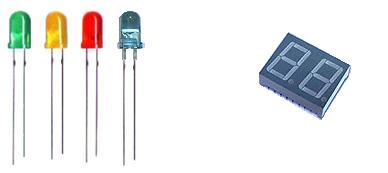
In general, LEDs of this type have a standard size range, the main parameter of which is the diameter of the circle of the lens or the width and thickness of the side if the lens is rectangular.
Lens Diameter, mm: 3; 4.8; 5; 8 and 10.
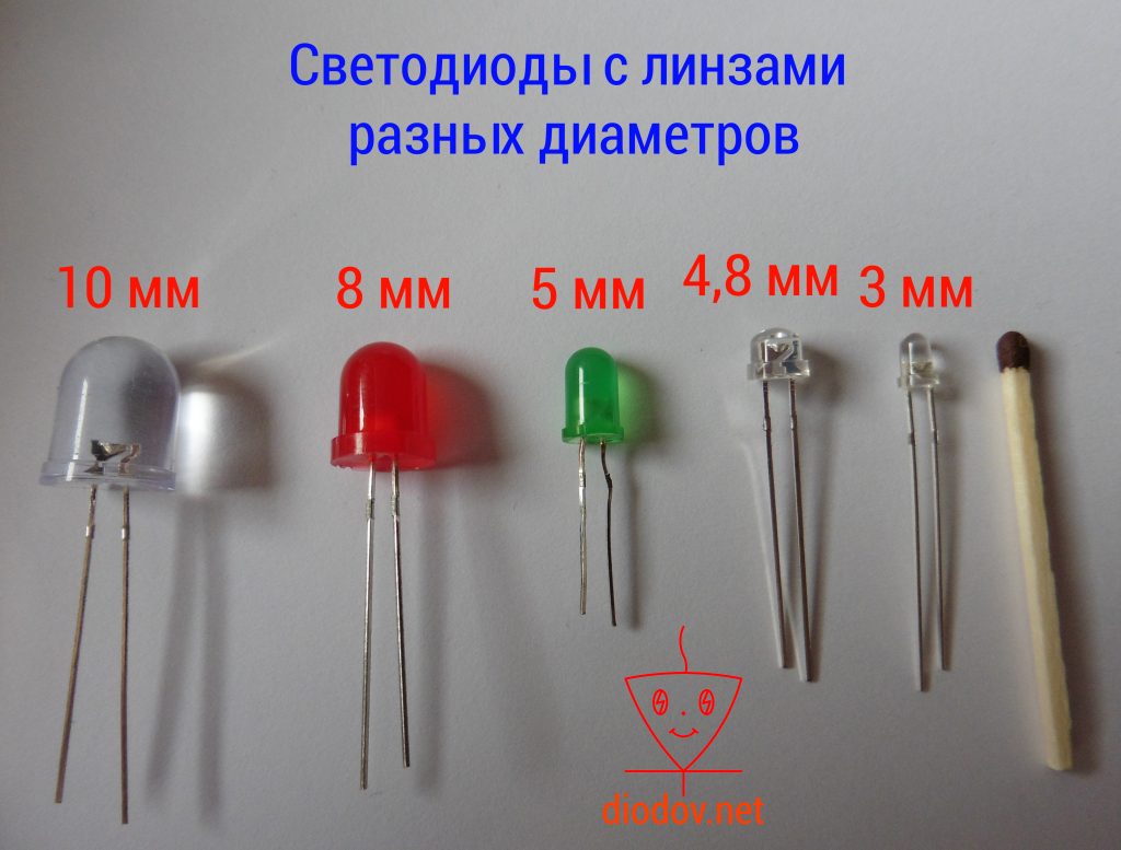
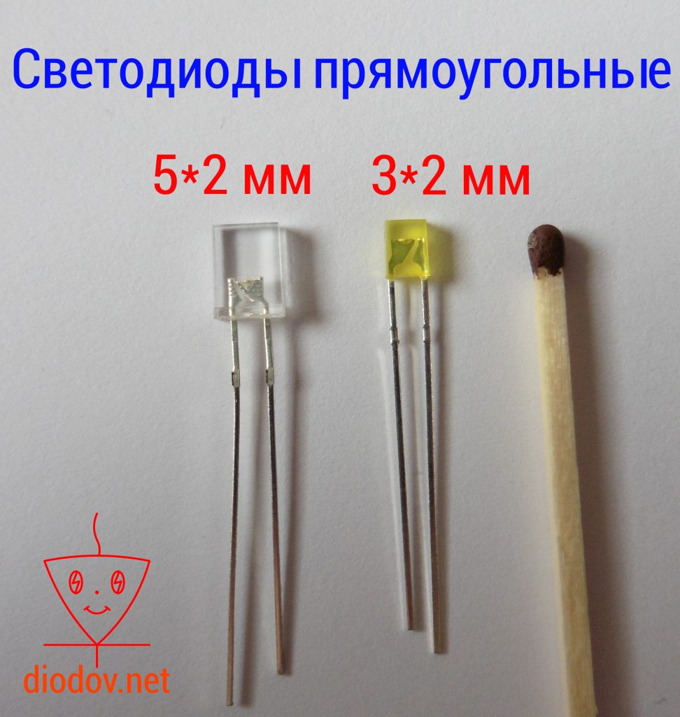
The sides of the rectangle, mm: 3 × 2; 5 × 2.
How to determine the LED parameters with a multimeter?
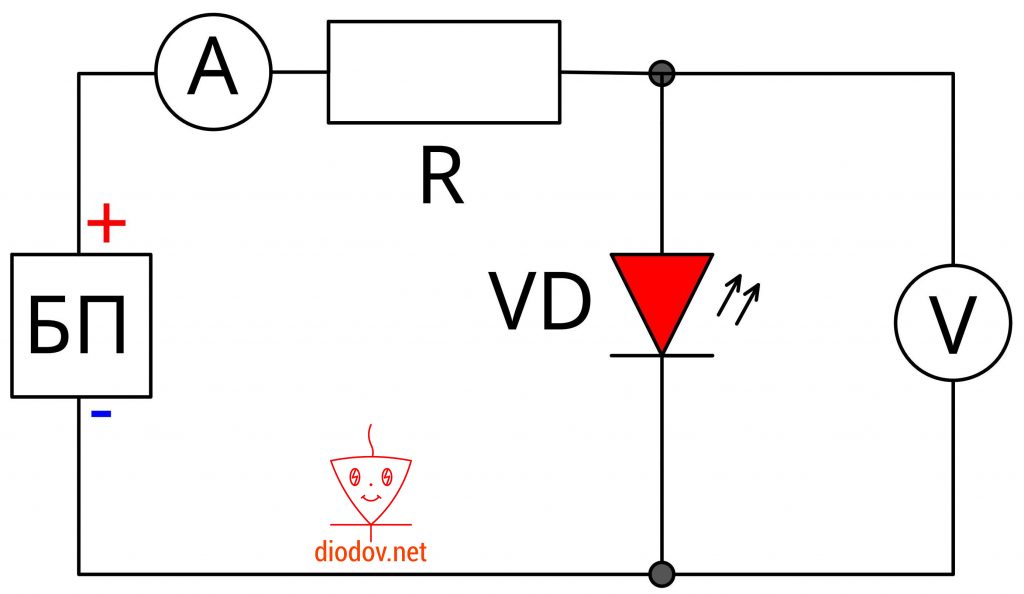
Now that we know that the rated current of many LEDs is 20 mA, it is quite simple to determine their voltage empirically. To do this, we need a power supply with voltage control and a multimeter. We connect the power supply in series with an LED and a multimeter previously set to current measurement mode.
The power supply should initially be set to the minimum value. Further, changing the magnitude of the voltage supplied to the LED, we set the current to 20 mA according to the multimeter. After that, we fix the value of the input voltage either by the standard voltmeter of the power supply or with the help of a multimeter set to voltage measurement mode.
To insure the LED, it is better to connect a 300 ohm resistor to it in series. But in this case, the voltage must be fixed directly to it.
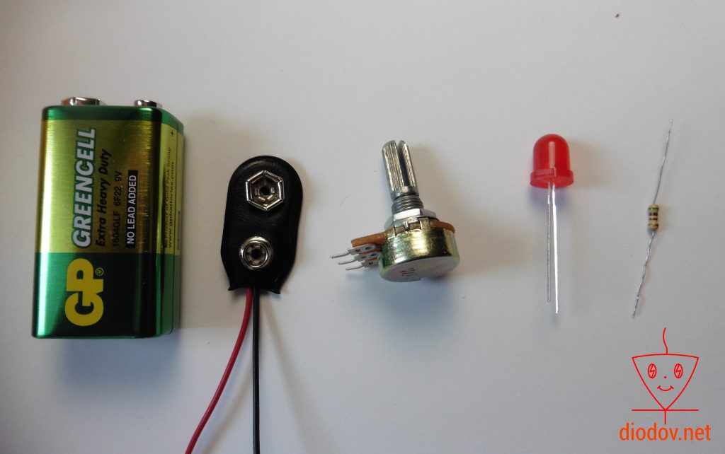
Since not everyone has a power supply with voltage control, it is possible to determine the parameters and serviceability of low-power LEDs using the following elements:
- Krone (9 V battery).
- 200 ohm resistor.
- Variable resistor, it is a 1 kOhm potentiometer.
- Multimeter.
The test LED is connected in series with the constant of the resistors, then with the variable, then with the crown and probes of the multimeter set to the direct current measurement mode.
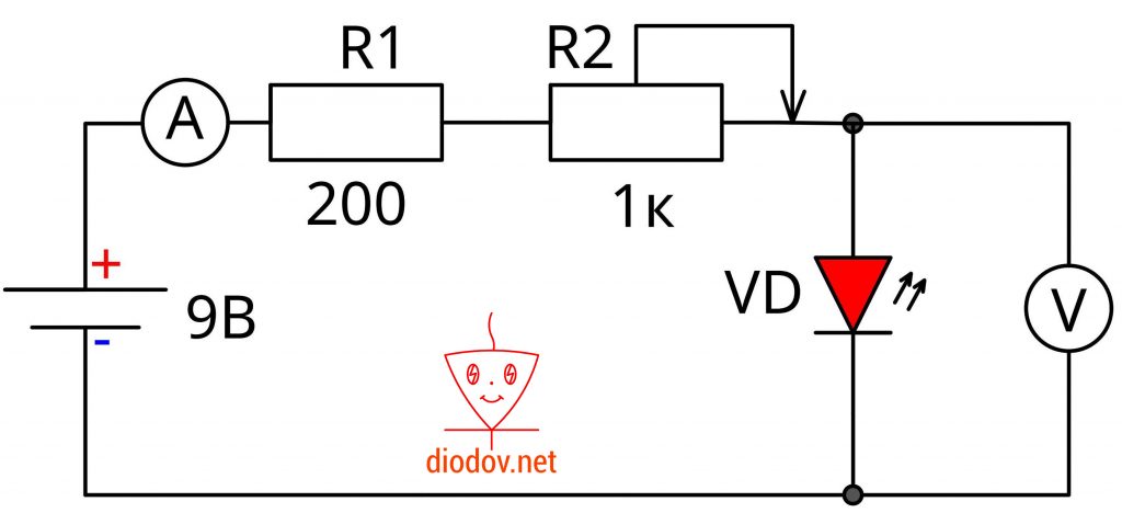
The sequence of connection of all elements does not matter, since the circuit is sequential, which means that the same current flows through all the components.
Initially, a minimum voltage should be set with a variable resistor, and then gradually increased until the current reaches 20 mA. After that, a voltage measurement is performed.
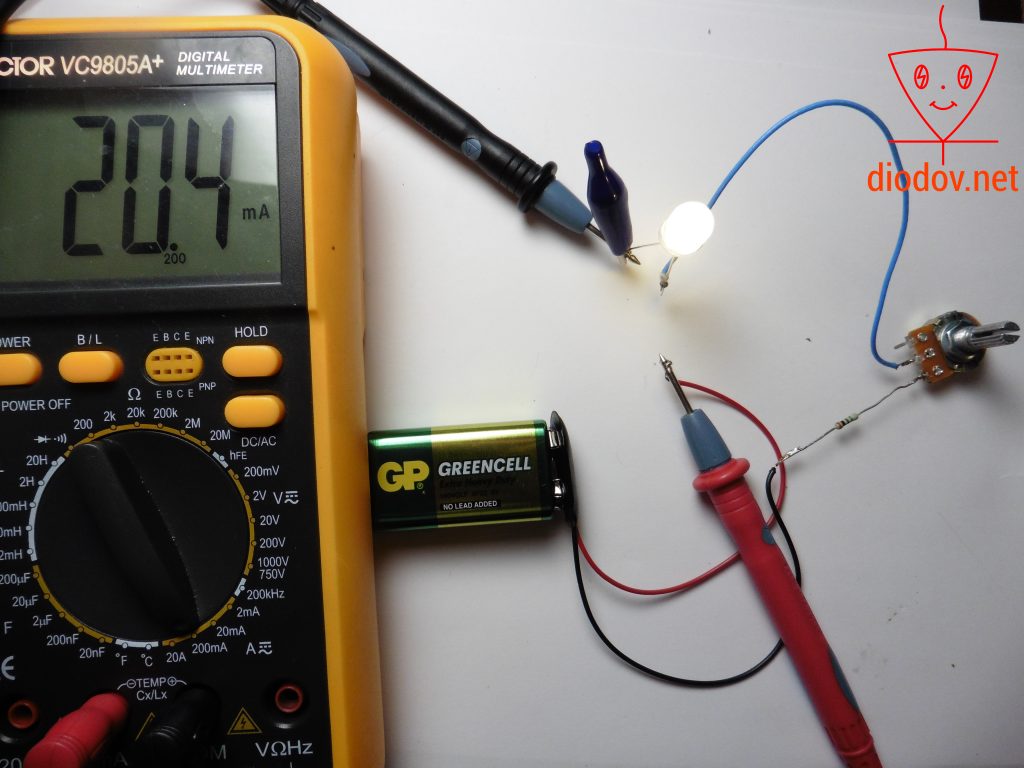
Using the above method, it will not be possible to determine the parameters of a powerful LED due to the flow of a significant current through the resistors. As a result, the latter may overheat. However, it is quite possible to determine its serviceability.
LEDs, or light emitting diodes (LEDs, in the English version LED - light emitting diode) - a semiconductor device that emits incoherent light when an electric current is passed through it. The work is based on the physical phenomenon of the occurrence of light radiation when an electric current passes through a p-n junction. The color of the glow (wavelength of the maximum of the emission spectrum) is determined by the type of semiconductor materials used that form the p-n junction.
Advantages
1. LEDs do not have any glass bulbs and filament, which provides high mechanical strength and reliability (shock and vibration resistance)
2. The absence of heating and high voltage guarantees high level electrical and fire safety
3. Inertia makes LEDs indispensable when high speed is required
4. Miniature
5. Long service life (durability)
6. High efficiency
7. Relatively low voltage and current consumption, low power consumption
8. A large number of different glow colors, radiation pattern
9. Adjustable intensity
disadvantages
1. relatively high cost. The money / lumen ratio for a conventional incandescent lamp is approximately 100 times that of LEDs
2. low luminous flux from one element
3. LED degradation over time
4. increased requirements for the supply source
Appearance and basic parameters
LEDs have several basic parameters.
1. Case Type
2. Typical (working) current
3. Voltage drop (working)
4. The color of the glow (wavelength, nm)
5. The angle of dispersion
Basically, the type of body is understood to mean the diameter and color of the bulb (lens). As you know, an LED is a semiconductor device that needs to be powered by current. So the current with which to power one or another LED is called typical. In this case, a certain voltage drops on the LED. The color of the radiation is determined by both the semiconductor materials used and the dopants. The most important elements used in LEDs are: Aluminum (Al), Gallium (Ga), Indium (In), Phosphorus (P), causing a glow in the range from red to yellow. Indium (In), Gallium (Ga), Nitrogen (N) are used to produce blue and green glows. In addition, if a phosphor is added to a crystal that causes a blue (blue) glow, then we will get a white color of the LED. The emission angle is also determined by the production characteristics of the materials, as well as the bulb (lens) of the LED.
Currently, LEDs have found application in the most different areas: LED lights, automotive lighting, advertising signs, LED panels and indicators, running lines and traffic lights, etc.
Scheme of inclusion and calculation of the necessary parameters:
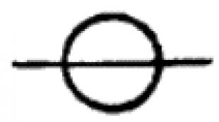
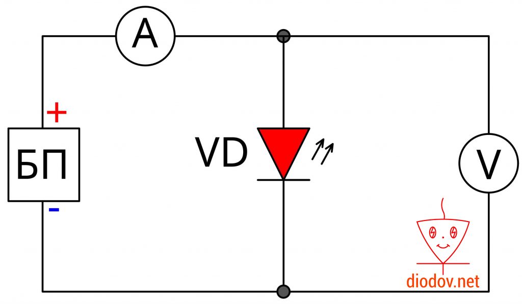
Since the LED is a semiconductor device, it is necessary to observe the polarity when connecting to the circuit. The LED has two outputs, one of which is the cathode ("minus"), and the other is the anode ("plus").
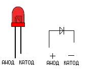
LED will be on only when turned on directly, as shown in the figure
When turned back on, the LED will not light. Moreover, failure of the LED is possible at low permissible reverse voltage values.
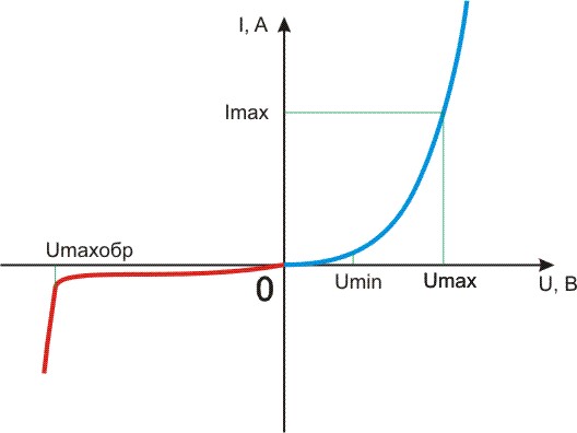
The voltage dependences of the current during forward (blue curve) and reverse (red curve) switching are shown in the following figure. It is not difficult to determine that each voltage value has its own current flowing through the diode. The higher the voltage, the higher the current value (and the higher the brightness). For each LED, there are permissible values \u200b\u200bof the supply voltage Umax and Umaxobr (respectively for direct and reverse switching). When voltages are applied above these values, an electrical breakdown occurs, as a result of which the LED fails. There is also a minimum value of the supply voltage Umin, at which the LED glows. The range of supply voltages between Umin and Umax is called the “working” zone, since it is here that the LED works.
 \
\
1. There is one LED, how to connect it correctly in the simplest case?
To connect the LED correctly in the simplest case, you need to connect it through a current-limiting resistor.
There is an LED with an operating voltage of 3 volts and an operating current of 20 mA. It is necessary to connect it to a source with a voltage of 5 volts.
We calculate the resistance of the current-limiting resistor
R \u003d U quenching / I LED
Extinguishing \u003d U supply - U LED
U power \u003d 5 V
U LED \u003d 3 V
R \u003d (5-3) /0.02\u003d 100 Ohms \u003d 0.1 kOhm
That is, you need to take a 100 Ohm resistor
2. How to connect multiple LEDs?
We connect several LEDs in series or in parallel, calculating the necessary resistances.
Example 1
There are LEDs with an operating voltage of 3 volts and an operating current of 20 mA. It is necessary to connect 3 LEDs to a source of 15 volts.
We calculate: 3 LEDs for 3 volts \u003d 9 volts, i.e. a 15 volt source is enough to turn on the LEDs in series
The calculation is similar to the previous example.
R \u003d U quenching / I LED
Power supply \u003d 15 V
U LED \u003d 3 V
I LED \u003d 20 mA \u003d 0.02 A
R \u003d (15-3 * 3) /0.02 \u003d 300 Ohm \u003d 0.3 kOhm
Example 2
Let there be LEDs with an operating voltage of 3 volts and an operating current of 20 mA. It is necessary to connect 4 LEDs to a source of 7 volts
We calculate: 4 LEDs for 3 volts \u003d 12 volts, so we don’t have enough voltage to connect the LEDs in series, so we will connect them in series-parallel. Divide them into two groups of 2 LEDs. Now we need to calculate the current-limiting resistors. Similarly to the previous paragraphs, we calculate the current-limiting resistors for each branch.
R \u003d U quenching / I LED
Extinguishing \u003d U supply - N * U LED
U power \u003d 7 V
U LED \u003d 3 V
I LED \u003d 20 mA \u003d 0.02 A
R \u003d (7-2 * 3) /0.02 \u003d 50 Ohm \u003d 0.05 kOhm
Since the LEDs in the branches have the same parameters, the resistance in the branches are the same.
Example 3
If there are LEDs of different brands, then we combine them in such a way that there are only ONE type of LEDs (or with the same operating current) in each branch. In this case, it is not necessary to observe the same stresses, because for each branch we calculate our own resistance
For example, there are 5 different LEDs:
1st red voltage 3 volts 20 mA
2nd green voltage 2.5 volts 20 mA
3rd blue voltage 3 volts 50 mA
4th white voltage 2.7 volts 50 mA
5th yellow voltage 3.5 volts 30 mA
Since we divide the LEDs into current groups
1) 1st and 2nd
2) 3rd and 4th
3) 5th
we calculate resistors for each branch
R \u003d U quenching / I LED
U blanking \u003d U power - (U LED Y + U LED X + ...)
U power \u003d 7 V
U LED1 \u003d 3 V
U LED2 \u003d 2.5 V
I LED \u003d 20 mA \u003d 0.02 A
R1 \u003d (7- (3 + 2.5)) / 0.02 \u003d 75 Ohms \u003d 0.075 kOhm
similarly
R2 \u003d 26 Ohm
R3 \u003d 117 ohms
Similarly, you can arrange any number of LEDs
Important notice!
When calculating the current-limiting resistance, numerical values \u200b\u200bare obtained that are not in the standard series of resistances, so we select a resistor with a resistance slightly larger than calculated.
3. What will happen if there is a voltage source with a voltage of 3 volts (or less) and an LED with an operating voltage of 3 volts?
It is permissible (BUT UNWANTED) to include an LED in the circuit without current limiting resistance. The cons are obvious - the brightness depends on the supply voltage. It is better to use dc-dc converters (voltage boosting converters).
4. Is it possible to turn on several LEDs with the same operating voltage of 3 volts parallel to each other to a source of 3 volts (or less)? In the "Chinese" lanterns, this is indeed done.
Again, this is permissible in amateur radio practice. The disadvantages of this inclusion: since the LEDs have a certain spread in parameters, the following picture will be observed, some will glow brighter and others dimmer, which is not aesthetic, which we observe in the above flashlights. It is better to use dc-dc converters (voltage boosting converters).
Important notice!
The above schemes do not differ in the high accuracy of the calculated parameters, this is due to the fact that when current flows through the LED, heat is generated in it, which leads to heating of the pn junction, the presence of current-limiting resistance reduces this effect, but the balance is established at a slightly increased current through the LED . Therefore, it is advisable to use current stabilizers rather than voltage stabilizers to ensure stability. When using current stabilizers, you can only connect one LED branch.
See other articles section.