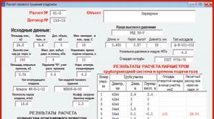
Schematic diagram VHF fm receiver all-wave. Simple all-wave VHF-FM radio
A bit of history.
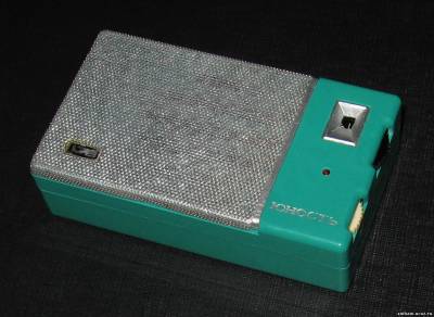
In the magazine Radio No. 9 for 1965 the radio designer "Youth" was described. It was one of the first Soviet kits for assembling a pocket radio receiver - a “transistor," as they were then called. He is dear to me, as a memory. This is exactly what my parents gave me in 1973. We bought it in the central department store of Melitopol, where we were visiting with my aunt. The case was a pleasant color of "sea wave" - \u200b\u200bas in the photograph on the site "Domestic Radio Engineering of the twentieth century."
If you have an isolated transformer, it serves secondary voltage up to about 220 volts. Ignore the classic part of the thread and you will only get disappointed and enough. If we launch any search engine on the Internet with the keywords “crystal set”, we will find many pages that have diagrams similar to the diagrams in the above figure, complete with design data and photographs. Most of the pages we find will be in English, because English is the universal language of the Internet, and most Americans, British and Australian fans love this hobby.
I collected it then, but my English teacher, Valery Nikolaevich, who himself was an avid radio amateur, helped me fix it. Later, in the case from this radio designer, I assembled the receiver according to a scheme very popular at the time. And then he was lost somewhere in space-time ...
With the help of colleagues with site "Domestic radio technology of the twentieth century"i managed to find a case from this constructor. Almost the same color, but completely empty. Later, it was possible to find two "half-bodies" of a later modification of this constructor - "Youth KP-101". The case, of course, is no longer so beautiful, but the sizes of the boards and installation accessories for both sets are the same. It was then that the idea arose to assemble a receiver in the case of the first “Youth”. Very few stations are currently broadcasting in the NE or DV bands, but, for example, about 30 are currently operating in the “upper” VHF band in St. Petersburg. So the choice was obvious - VHF receiver for receiving stations in the range of 87.5 ... 108.0 MHz.
Of these, the tradition and practice of crystal radio stations, so rallies and prize competitions are organized in which all the characteristics of the sensitivity and selectivity of complex devices are tested, all work strictly without batteries, but are able to receive transmissions in medium and short waves over thousands of kilometers! This widespread passion brings with it certain advantages for Anglo-Saxon beginners, for example, extensive literature that includes hundreds of items, many associations and, finally, the ability to find on the market all the necessary materials from all mounting boxes to individual components, detectors, variable capacitors, wire, headphones and all that is necessary for successful participation in the construction of a crystal receiver.
Receiver circuit.
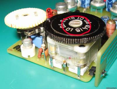
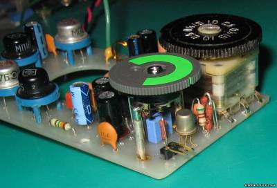
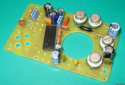
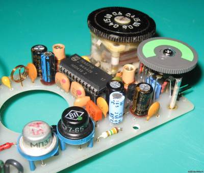
The next stage is the development of the concept. A completely transistor version was not even considered, since it is very difficult to configure. I also did not consider ICs with a low IF (KR174XA34, TDA7021 and others like them) - I already had experience in designing receivers for them and I did not like these devices. Therefore, one solution suggested itself - superheterodyne on the "single-chip" IC receiver. There are a great many microcircuits of this class, the parameters for all of them are approximately the same. Therefore, when choosing, I was guided by its availability, price, “binding” and ease of setup. For all these parameters I liked the most TEA5710. Moreover, there was already a positive experience in manufacturing receivers on it (Fig. 2, 3).
Well, here we are not here yet. Anyone who wants to make a galenic radio from scratch is likely to encounter a number of practical problems that even the toughest can ward off. But there is no fear: we Here we will present, in addition to the diagrams, a possible set of solutions from the most economical and random to the original original original material, beautiful and expensive. Purchasing a kit can also be a quick and economical way to get the basic components needed to assemble them.
On the pages of this theory it was possible to determine the function of the individual components. But what are the really irreplaceable things? Believe me, this question has been formulated several times in real life, so a hobby is born in a hobby: it is the creation of receivers using means of good luck: the so-called crystal sets of fox holes.
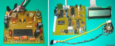
Fig. 2 Fig. 3
In the strapping of this IC, two band-pass filters and a detector on a piezoceramic discriminator are used. This allows you to get a fully configured node "UPCH-detector" ... generally without setting it up. And this makes it very, very easy to set up the receiver as a whole. In fact, all that remains is to arrange the range and adjust the uniformity of gain throughout the range. In principle, this can be done even without instruments, “by ear”.
But this is a topic that deserves a speech. To return to the truly irreplaceable parts, we can try a priority-ranked approach, of course, given that based on what you have, you can choose a variant of the scheme and not another one, and yet The best results can only be achieved using the highest quality components. A high impedance headset is perhaps the most important element along with a detector. One good headset can still be found in markets or on the Internet. very good characteristics, and it’s also nice to see that the Marcon look, a high-quality ceramic headset costs a lot less and provides similar results. Unfortunately, it is not sold in Italian stores, but it can be found on the Internet at variable prices. Variable capacitor - a variable element is needed to accommodate the stations, but for this element is not a capacitor. However, it is not difficult to get a good capacitor, which varies from several hundred picofarads, but we can build a variable inductor system, as we will do in the first proposed receiver. The best variable capacitors are "airborne", such as those installed in old radio labs, but the miniature ones installed on transistor radios are wonderful. 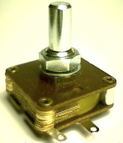
- It would be nice to have one or at least a high-quality headset.
- Detector.
- In order of importance, the detector dominates, being the heart of the radio.
The TEM5710 switching circuit is standard, from a datasheet. Some moments "spied" in the book B.Yu. Semenova "Modern do-it-yourself tuner". In particular, the node of the buffer cascade for connecting a digital scale. He helped me a lot when I carried out the first tuning of the finished receiver - he specified the parameters of the local oscillator coils and capacitors and the preselector. In principle, this node can not be assembled - just leave empty places on the board. If you make coils according to the given recommendations, and the KPE overlap will not differ much from that indicated on the diagram, then, with a high degree of probability, you will “fall into” the desired range.
Connection points between components and wires can be made using brass screws and washers. Those familiar with the tin welder can make welders that are safer and more reliable, but they will not have to overheat the dihedral compound with germanium, which is very sensitive at high temperatures.
From left to right you can recognize: antenna and ground, tuning coil with parallel capacitor, detector diode and headphones. The most interesting element of this circuit is the variable inductance, which is activated. It is also useful to observe and compare the diagram of the practical assembly, bearing in mind that this is an optional offer, and that any other practical solution will be equally good, provided that the links are followed.
The second half of the receiver is ULF. At first I wanted to collect it on some low-power IC ULF. I rummaged through a lot of literature and reference books, but, to my surprise, I didn’t find anything suitable ... Either stereo (but you need mono), then the power is large, then the supply voltage is not suitable, then the current consumption is large, then the “planar” case but I wanted DIP), then I can’t find it in stores in principle ... In general, in the end I decided to do ULF on discrete elements. At first there was an idea to make a transformer, as in the original "Youth". But he quickly abandoned it, because finding transformers in our time is not easy. Then there was the idea to make on modern transistors. And then I accidentally stumbled upon a circuit on old MP shks with very good parameters. I assembled the layout of this amplifier, drove it in different modes, “listened” to the oscilloscope and I liked how it plays music. And the issue with ULF was resolved in favor of this amplifier.
The first thing to do is make a tuning coil. And “have a good time and patience” for operations, because it depends on the aesthetic and functional result of our device. To get a good result, you should follow some tricks. To get started, select a support tube that is stiff enough. Make sure it is tough enough and not prone to crumbling when handling it. On this tube, the winding of 180 spiers should be well aligned and hardened. You may want to “wind” the enamel wire before starting the winding, fixing it to the boss on a solid support and pulling on another clamp to feel some kind of failure, but without exaggeration, otherwise it will break.
As a result, such a receiver circuit was “born” (Fig. 4) .
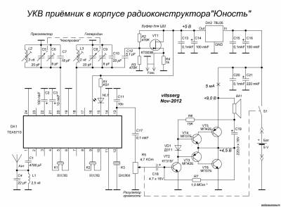
Actually, it makes no sense to describe her work. The receiving part is comprehensively described in the datasheet on the IC TEA5710 (and in the mentioned book of Semenov). ULF is described in detail in the mentioned article by Polyakov (all this is in the archive - link above). I note only a few points.
This operation can be repeated for different sections of the wire during winding. The initial end should be firmly fixed in the tube with a hole and a little mastic. During the operation, push the nails with twisted wires so that they are compact. Finally, drill a second hole in the tube and skip the second end of the wrapper so that it is securely attached to it, and now the coil is ready for fastening to the support. a place.
The second and last delicate element is the slider, which is used to change the inductance of the coil and, therefore, the matching frequency. You can use a light but elastic strip for the sheet: turning around the house, it is easy to find something suitable, for example, starting with a tin can, which can be easily cut with scissors. It serves as a width of 5 cm and a length of about 15 cm, it is cleaned along the edges of the sandpaper, then folded to make a similar appearance on one side in the figure: on the one hand, it should be attached to the support with a pin screw, and the other should will creep along the coil, providing a certain contact pressure.
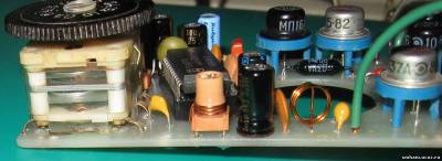
The power supply of the IC TEA5710 is carried out from +5 V, for which purpose the voltage regulator for the IC 78L05 is assembled on the board (elements C13 C14 DA2 C15 C16). From it, the buffer cascade for the digital scale is powered (elements C12 R2 R3 VT1 R4). As already noted, if the scale is not planned to be connected, then these elements can simply not be installed on the board. No jumpers or alterations are needed.
In short, you need to make a small miracle of practical technique! After completion and verification, the slider should be locked in place and rotated to mark the contact path on the coil. This path will be cleaned with care by enamel using a medium-sized piece of sandpaper. Now we are ready to connect other components. The end result should look like the image below.
The most exciting phase begins: functional testing. First, you need to connect good antenna and "good land." The land must be made using some sort of home conduit. The wire section is connected to a thermo isophone, trying to achieve good electrical contact and is provided by the other part of the crocodile tweezers. Instead, the antenna should be made using a wire insulated with a length of at least 20 meters, thrown out of the window or lowered from the roof.
The receiver IC itself is “rigidly” switched to “FM” mode (the 14th leg is connected to ground). There is also an AM path in the TEA5710, but in this case it is not used. The HL1 LED is a fine tuning indicator. It is better to use a red LED with a diameter of 3 mm. I managed to "squeeze" it between the control knobs and the volume control.
In short, the important thing is that it is long, isolated and as tall as possible. By connecting it to one or another point, different results are obtained for the sensitivity and selectivity of the device. It should be possible to hear at least a rustle. By moving the cursor to the coil, we are very likely to tune one or two radio stations, possibly partially overlapping. By doing this test at night, the number of stations increases, but it becomes almost impossible to separate them. During the experiments, let's also feel free to enter options in the connections, for example, exchange the antenna with the ground or connect headphones at different points.
Printed circuit board.
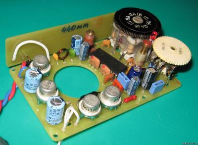
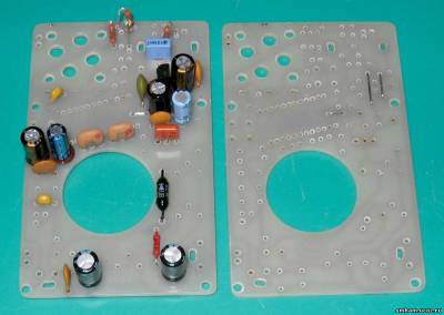
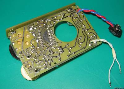
Based on this scheme, a printed circuit board was developed that is exactly the same size as the “original” Youth board - 86 x 53 mm (Fig. 5).
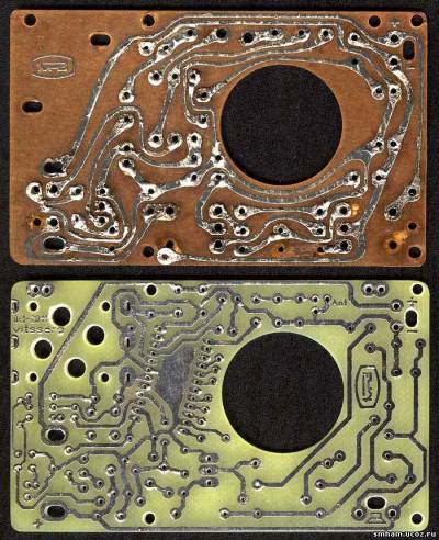
It is quite difficult to develop a board for which dimensions, holes for mounting in the case and for the speaker, as well as the location of the controls (volume control and KPI settings) are already determined ... For a very long time I was “tormented” with the placement of ICs. Sometimes, there was a great desire to “break” her ... J Well, she didn’t “fit in” in any way ... And the wiring requirements are quite contradictory. On the one hand, the coils of the preselector and the local oscillator should be maximally spaced, on the other hand, they should be placed closer to the KPI and the IC, which does not fit anyway ... And also the wiring of the “common” wire ... But everything turned out to be more or less normal when I realized turning the case IMS, literally, a few degrees clockwise. There were few jumpers, only 3 pcs., But they are ...
That is why all these elements are fixed with crocodile tweezers. The newly realized sample is what is usually found in the "training" boxes of American or French. In fact, this is a rather rudimentary receiver, capable of giving only a pale idea of \u200b\u200bwhat can be done using crystal radio. And this is not very selective, but it is also not very reasonable, but it is an important starting point, because it is done in the afternoon, it certainly works and allows at least checking the headset and detector, and is also very suitable for presentation as Creative game for children guided by parents or teachers.
The drawing of the board is made in the format of the program "Sprint Layout - 5". in the file directory.
In addition, in the same there are many reference and other material designed to help in the work on the creation of the receiver.
The board is made of single-sided foil fiberglass with a thickness of 1.5 mm by the LUT method. All holes must be drilled. before trimming boards “in size”, since the mounting holes are located on the very edge of the board and when carelessly drilled, you can simply break it. Next, the board needs to be cleaned with a fine sandpaper (1000 ... 2000), tinned and washed with alcohol (acetone).
Those who really want to do this, of course, will not stop at this stage, but want to create more efficient devices, possibly capable of receiving dozens of foreign stations with good sensitivity. To get these results, first of all, we need to understand what is happening in the first editing, and then conduct subsequent experiments with a certain degree of knowledge. We are trying to analyze from a technical point of view the circuit we just built in to identify defects.
The antenna connects directly to the tuner coil and thus affects tuning. The detector is connected to the end of the coil, which is a high impedance point; thus, “charging” the tuned circuit, reducing its selectivity; The slider settings system does not provide stable and secure contact; creeping contacts always introduce a certain signal loss. In addition, in most cases, contact does not occur on the loop, but between two turns, realizing a short circuit in the tuner coil, which reduces the sensitivity of the receiver. Although the receiver is working, and that was the goal that we set for this first experimental test.
KPI - from the Chinese receiver. It has 2 sections for AM (which are not used), 2 sections for VHF with a maximum capacity of approximately 20 pF and 4 trimmers with a maximum capacity of 8 pF. Conclusions KPIs are the main fixing element, since KPI itself is attached to the board "vice versa.
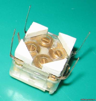
Piezoceramic filters (Fig. 7), you can use any band-pass ( not notch - pay attention to this!) At 10.7 MHz. Also present in many Chinese receivers. Sometimes found in conventional and online stores. Like the piezoceramic discriminator. Here it is, perhaps, may be the most scarce part in this receiver. Also pay attention that this NOT QUARTZ!
Coils There are only three of them (Fig. 8).
L1 - frameless, contains 2.5 turns of wire PEL or PEV with a diameter of 0.4 ... 0.6 mm. The coil is wound on a mandrel with a diameter of 6 mm (for example, a drill shank). No settings required. After installation on the board, you can fix it with a few drops of paraffin (drip from a burning candle).
L2 - contains 3 turns of wire PEL or SEW with a diameter of 0.4 ... 0.6 mm
L3 - contains 2 turns of wire PEL or PEV with a diameter of 0.4 ... 0.6 mm
L2 and L3 are wound on polystyrene frames with a diameter of 5 mm with a trimming core made of copper or brass, M3 or M4. If you find frames with a groove, that's even better. After winding, before installing on the board, it is desirable to fix the turns with paraffin.
Transistors in the ULF (Fig. 9), you can use any of the series P10 - P16, MP37 - MP42 of the corresponding conductivity. It is necessary to pick up in pairs with close coefficients. Gain VT3-VT4 and VT5-VT6. For their installation, it is advisable to use plastic stands.
Resistors - any output power of 0.125 ... 0.25 watts.
Variable resistor - domestic or imported ("wheel") with a switch, resistance 4.7 - 47 kOhm.
Capacitors (non-polar) - small-sized ceramic. As C17, it is desirable to apply film. Electrolytes - any high-quality (usually imported).
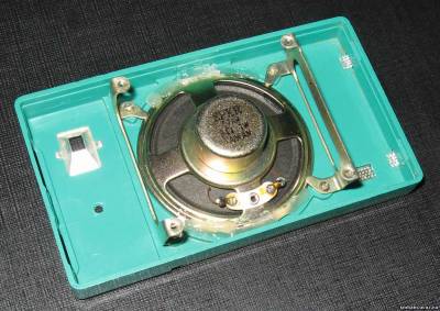
Loudspeaker - domestic (0.1 GD-6, 0.2 GD-1, etc.) or imported (I used an 8-Ohm speaker from the old PC system unit) with a resistance of 6 - 8 Ohms and suitable dimensions.
Antenna - telescopic, 400 - 600 mm - which you will find, suitable in size and design.
Assembly and setup.
Assembly and adjustment is preferably carried out in approximately this order.
First, solder the three jumpers (Fig. 13). Then we install all the constant resistors and capacitors, IF filters, wrap and solder all the circuits. In a word, all passive components. We install the stabilizer IC on the board and check the output voltage - it should be. + 5 V. Before the first start-up, it is advisable to wash the board on the soldering side with alcohol. After that, we install VLF transistors (VT2 ... VT6), matched in pairs. We check everything again. Instead of R7, we temporarily turn on a constant resistor of 1.0 MΩ, plus a tuning resistor of 470 Com in series with it.
We connect the speaker, “minus” C18 we short-circuit to the ground, we connect “Krona”. Next, we connect a milliammeter at the “20 mA” limit instead of the power switch and check the current consumption of the amplifier. He must about 5 mA. Next, instead of the power switch, temporarily put a jumper and control the voltage at the "minus" C19. It should be half the supply voltage. We achieve this by selecting R7 (changing the resistance of the tuning resistor). Then we measure the total resistance and solder a constant resistor. I got about 1.3 megohms.
After that, you can “listen” to it with a generator and an oscilloscope, or simply send a signal from any source, for example, the same PC. Naturally, minus C18 before this must be torn off the ground. The amplifier should sound loud and clear, without overtones and audible distortions (and it “screams” very strongly!).
Next, install the KPI and a variable resistor. This is perhaps the most difficult stage when installing the receiver. KPIs are different heights. Therefore, it is better to do so. We determine where he has the conclusions of the FM sections. The easiest way is with a capacity meter. If it is not there, then, with a high degree of probability, they are on the side where the conclusion was drawn in the upper part of the KPI (circled in red in the photo) (Fig. 14).
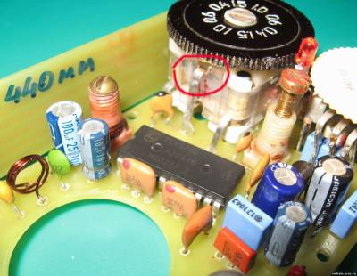
The tuning dial from Yunost has exactly the same seat as on the imported KPI, but for the “native” KPI it is fixed with an M3 screw with a countersunk head, and in the imported one - with an M2.5 screw. I put a washer made of soft material under the screw (for example, it can be made of cambric) and the limb was well fixed (circled in red in Fig. 6).
Next, install the KPI on the board without soldering, and install the board in the case and be sure to fix it with fixing screws. We set the desired position of the KPI and determine how much it needs to be raised above the board. In my case, it turned out that it was 3 mm. Next, I cut out 4 small corners of plastic with a thickness of 3 mm and glued them with dichloroethane to the CPA (Fig. 15).
We set the trimmers in the middle position, again install the KPI on the board and fix it in the case. If everything has risen as needed, solder the KPI right in place. You can additionally “grab” it to the board with a few drops of hot glue from the gun.
Similar "torment" is coming with a variable resistor. The findings must first be lengthened with wires. Also, its installation must be done "in place" (Fig. 16).
Only after that it is possible to install the IC TEM 5710. You can simply solder it into the board, or you can install it on the socket. I did not come across 24-foot panels with a step of 1.778 mm and a raster of 10 mm, but without problems you can find a 30-foot. Removing the "extra" 6 contacts, we get what we need.
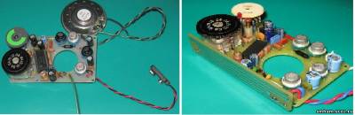
Fig. 17 Fig. 18
Once again, we very thoroughly wash the circuit board from the flux residues and “through the gap” we look through all the rations in the IC area. We solder the power block, loudspeaker and antenna - a piece of wire half a meter long - meter (Fig. 17). After making sure that there are no random jumpers between the tracks, turn on the receiver. Immediately we should hear a characteristic "hiss". You need to try to tune in to any station and decide which part of the range we are in. This is where the digital scale, which can be connected to the buffer cascade on the field effect transistor, can help a lot. In the absence of a digital scale or frequency counter, you can try to tune the receiver using an industrial receiver.
Turn the KPI setting dial counterclockwise until it stops and with the help of tuning local oscillator coils L3 tune in to the most " lower"Station of the band (87.5 MHz, in St. Petersburg it is" Road Radio "). Then turn the KPI clockwise until it stops and with trimmer C9 tune in to the station " top"Station (in St. Petersburg it is Russian Radio, 107.8 MHz). Such adjustments need to be repeated several times, since they are interdependent.
The preselector is configured in the same way: “below” - by the L2 coil, “above” - by C6 trimmer according to the maximum undistorted volume of the stations. For finer tuning, the antenna length can be reduced.
The L1 coil does not need to be tuned.
A bit about the antenna. First, I decided to make a “print” and install it in the same place where the magnetic one stood in the “original” Youth. For fastening I used 2 double wire corners. In antennas, to put it mildly, I'm not strong, so I just drew 2 options in the form of "snakes". The total length of the conductor of one snake turned out to be 440 mm, the other - 390 mm. But it turned out that these antennas work very poorly ... I tried both, selected the parameters of the circuits, tried to make them look like a "dipole" - all in vain. Perhaps there are printed antennas for this range, maybe you need to make the correct coordination - I don’t know, I repeat, I’m not strong in antennas. So far, I see only one solution - a telescopic antenna. And I don’t want to “leak” the case ... (Fig. 18, 19).
Although, I already had to make one hole - for the fine-tuning LED (between the tuning dial and the volume control - everything is “on the edge of a foul” in placement). It must also be installed in place, after preliminary marking the hole in the top cover of the receiver.
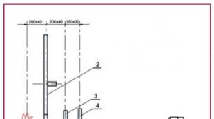
Next, install the board in the case using the standard “Youth” brackets. (Fig. 20). Under mounting screws that are closer to the KPI and volume control, be sure to lay washers made of insulating material.
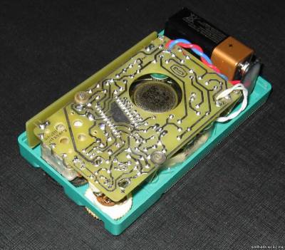
Close the back cover and enjoy our work (Fig. 21). J Mounting a telescopic antenna is someone who wants to and who finds what antenna ...
Vican Sergey Viktorovich
Saint Petersburg,
December 19, 2012.
Simplest VHF FM receiver, available for repetition to a beginner amateur, can be assembled according to the scheme of a single-transistor synchronous-phase detector. The schematic diagram of such a receiver is shown in the figure.
The signal is received by the WA 1 antenna, the role of which can be performed by a piece of the wire. This signal enters the oscillating circuit L1C2, adjusting the capacitor C2, the circuit can be tuned within the VHF FM range 65.8-73 MHz. The signal voltage allocated by this circuit enters through the capacitor C3 to the base of the transistor VT1. This transistor stage simultaneously performs several functions: the functions of a phase detector, a low-pass filter, a DC amplifier and a low-frequency amplifier. Phase detection occurs at the pn junction of the transistor, equivalent to the junction of the diodes. You can assemble the receiver by volume mounting, or you can develop a printed circuit board based on a circuit diagram, and arrange the parts on it in the same order as on the diagram. Coil L1 does not have a frame; for winding, a shank of a drill with a diameter of 7 mm is taken and a coil is wound on it with a PEV wire of 0.4 ... 0.5 mm. Coil L1 contains 14 turns. After winding, the drill is removed from the coil (it serves only as a mandrel for winding).
The P416B transistor can be replaced with a GT308A, KT603B. Phone - any high-resistance small-sized. Capacitor C2 type CPC - ceramic, at 8 ... 30p, 5 ... 20r or 4 ... 15r, it is adjusted by rotating the screw located in the middle. As a power source, you can use a 9V Krona battery. Any switch, for example, a toggle switch.
Customization relatively simple. You need to connect the phone, power and antenna - a piece of the wire, the longer the better. It is advisable to hang the antenna out of the window or hang it on the window frame. Now you need to put on the head phones (they should have a weak hiss) and try to catch one station by rotating the rotor of the capacitor C2. If this does not work out, you need to slightly stretch the turns of the coil and repeat.
Good results from such a simple receiver cannot be achieved, but it can receive two or three stations in the VHF FM band. Experiment with stretching and compressing the turns of the L1 coil, the length and location of the antenna, and the supply voltage. Instead of headphones, you can connect a 1 ... 3 kΩ resistor and apply low-frequency voltage to the VLF from the connection point of this resistor and the emitter of the transistor, then you can listen to the speakers.
List of Radio Elements
| Designation | A type | Face value | number | Note | Score | My notebook |
|---|---|---|---|---|---|---|
| VT1 | Bipolar transistor | P416B | 1 | Search in Chip & Dip | In notebook | |
| C1 | Capacitor | 12 pF | 1 | Search in Chip & Dip | In notebook | |
| C2 | Variable capacitor | 8-30 pF | 1 |