Red green LED. Two-color LED. Feature
And red-orange, scientists were able to create a yellow LED. He is third in the layout of white light and energetically close to orange. Without yellow, it would be difficult to imagine a complete picture of the world, so it is actively used in devices of modern devices.
New horizons for yellow
The yellow LED was invented shortly after the red. It is symbolic that the author of the invention was George Kraford, a student of the "father of LEDs" Nick Holonyak.
This happened in the 70s and was accompanied by the gradual introduction of new devices into human life. The first application was mainly associated with the backlight. Calculators, signboards, telephones shone in yellow, it was actively used in traffic lights. And now such an application of the LED exists, but other horizons have opened up besides it.
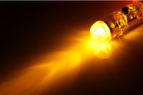
Characteristics of the yellow LED
For all LEDs, the main characteristics are wavelength and operating voltage (or permissible current strength). For a device emitting yellow light, these values \u200b\u200bare respectively 570-590 nm and 2.1-2.18 Volts.
The material for their production is gallium arsenide phosphide and several other semiconductors.
If you remove heat from the yellow LED and make sure that only the permissible stable constant current passes through it, then it can work continuously for more than 9 years. Ideal conditions do not exist, therefore, over time, the quality of lighting decreases, and the actual life becomes a little less. But when compared with all other existing lighting devices - this is the longest life.
The yellow LED may have different shades. There is an amber color (Amber), pure (High Yellow) and the like. This difference is due to the peculiarities of growing semiconductor crystals and the peculiarity of the design of the bulb. For example, a flask painted bright yellow will affect the light reaching our eyes.
Application options
The most common yellow LED received in the lighting fixtures for the car. Famous manufacturers such as Philips or OSRAM use it in the manufacture of turning lights and are developing high-power designs. Moreover, the competition in the automotive LED market is quite large.
Wide application of a gentle yellow LED for decorative purposes:
- curtains made of light bulbs, forming a beautiful colored rain;
- garlands adorn trees, building facades, street sculptures;
- lEDs replace candles, fully simulating their radiance;
- in spotlights to create club lighting when directed to a mirror ball;
- for lighting studios during photo or video shooting.
The light from the yellow LEDs creates a festive mood. They consume very little electricity, so they are quietly used in large areas.
There are prospects for the use of yellow light in medicine, since it is believed that it positively affects visual acuity, increases the speed of perception and contributes to the proper functioning of the lymphatic system.
A bright color can be seen from afar and attracts increased attention, so it is used to create information boards, signage plates and traffic lights.
Some lighting fixtures are designed so that they can combine the light of a yellow LED with white. In this way, it is possible to obtain the necessary light temperature of lighting.
Two-color LEDs contain on a single crystal two separate light emitters, which are made of different semiconductor alloys. Such an indicator can glow at least in two different colors. Why “at least”? Because due to the general case made of light-scattering plastic, with the simultaneous inclusion of both emitters, you can get the total third color.
In Tab. 2.5 lists the combination of shades encountered in two-color LEDs. It must be clearly understood that not all color mixtures differ visually well. For example, the combination “yellow - green” in a mixture is better not to use, because ambiguity is lost, because the total “green-yellow” tint is difficult without the skill to distinguish from green and yellow.
Table 2.5, Color Combinations in Two-Color LEDs
The perception of color by a person is very subjective. In colorimetry (the science of color), more than a thousand samples of color standards, standardized in special atlas books, are distinguished. Some people have the gift of “absolute color,” but this is as rare as the “absolute pitch” of musicians. In practice, the user can clearly distinguish between shades, but only with the simultaneous presentation of several samples for comparison.
LEDs form a fairly dim color saturation. If you take a mixture of red and green, then the total should be yellow. However, in the LED version, a shade is formed, which some perceive as "orange-yellow", others as "yellow-green." Moreover, if you look at the LED perpendicularly directly, then the yellow color is visible, but when viewed from the right side, the shade “blushes”, and from the left - “turns green” or vice versa.
Conclusion - it is necessary to design the device so that at least one exemplary indicator of the base color constantly glows on the panel, by which the remaining shades can be stably identified. They are usually served by a green power-on LED. Another option is to assign a different place to each indicator, approximately like in a traffic light - “red-yellow-green” or enter a blinking mode for the total color.
The direct voltage drop of two-color LEDs is the same as that of conventional LEDs of the same shade. You can navigate by the conditional point of the initial rise of the I-V characteristic: 1.6 V (red), 1.7 V (yellow / orange), 1.8 V (green), 3.5 V (white / blue). Any two-color LED can be replaced by two ordinary, adjacent or covered with a common housing, if you make electrical connections between them according to the internal circuit.
The color scheme of outdoor indicators should be selected according to the rules of ergonomics. For example, red indicates the status of "Accident", "Marriage", green - "Norm", "Readiness", "Work". Changing the Standby / Active modes can be indicated in yellow / green. "Blue" LEDs look good in the twilight or are used for decorative illumination of dark surfaces. And further. Green and red are considered to be smart Christmas colors, while black and orange are Halloween warning colors.
Two-color LEDs are two three output. The first of them have a counter-parallel connection (Fig. 2.15, a ... g), and the second - two separate emitters with a common anode / cathode (Fig. 2.16, a ... k). In all subsequent circuits, for simplicity, it will be assumed that the LEDs are “red-green”.
An important nuance. Usually, in three-output LEDs, the common contact is structurally located in the center of the case, but sometimes there are models, for example, BL-Bxx204-A (Bright LED Electronics), in which the common output is located at the edge. You can determine “what is what” by tapping the conclusions with an ohmmeter.
a) on the two MK lines, antiphase levels HIGH-LOW or LOW-HIGH are formed. Accordingly, the HL1 LED shines either red or green. For complete dimming of the LED, it is necessary to set the same levels at the MK outputs: LOW-LOW or HIGH-HIGH;
b) control of the HL1 LED from one MK line: HIGH - red, LOW - green, input with Z-state - complete blanking. The disadvantage of the circuit is excessive power consumption on the divider R1, R2, which is justified if the reference level from the midpoint is used for other nodes of the device;
c) similar to Fig. 2.15, b, but with less power loss, because no excess current flows through the Zener diodes VD1, VD2. Resistor R1 adjusts the overall brightness;
d) similar to Fig. 2.15, c, but with the possibility of separately controlling the brightness of the red and green light emitters with resistors R1, R2;
d) similar to Fig. 2.15, c, but with reduced power and the replacement of two zener diodes with transistor switches F77, VT2. Resistor & 2 adjusts the overall brightness; ABOUT
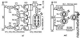
About Fig. 2.15. Connection schemes for two-color LEDs with two leads (end):
f) switching the polarity of the inclusion of a bright LED HL1 through a bridge circuit. The signals at the MK outputs must be strictly out of phase. Resistor R5 protects the pairs of transistors VT3, VT4 and VT5, VT6 from overcurrent when they are turned on simultaneously due to errors in the program, as well as during transient processes. Resistor R6 sets the brightness of the glow;
g) control of three two-color LEDs HL1 ... HL3 from three lines MK. One-color and multi-colored combinations of glow in any order are possible.
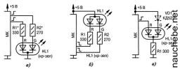
Fig. 2.16. Connection schemes for two-color LEDs with three leads (start):
a) at HIGH level at one of the MK outputs, the HL1 LED lights up in red or green. At two HIGH LEVELS should get a color close to yellow. Its real hue depends on the type of LED and the ratio of the resistances of the resistors R1, R2. At both LOW levels at the outputs of the MK, the LED is completely off;
b) similar to Fig. 2.16, a, but for the HL1 LED with a common anode and with active LOW levels;
c) at a LOW level at the MK output, the HL1 indicator glows green, at HIGH it turns red, since a “green” emitter (1.8 V) is shunted by “red” (1.6 V). The VD1 diode eliminates the small backlight of the "green" emitter with a luminous "red"; ABOUT

d) similar to Fig. 2.16, c, but for the HL1 LED with a common anode and with an active LOW level. Diode VD1 may be missing (experimentally verified). If you interchange the terminals “R” and “G” of the indicator HL1, then the presence of the diode VD1 is mandatory;
d) one common resistor to two emitters of the LED HL /, which can lead to some difference in the brightness of their glow. To obtain intermediate color shades, two antiphase PWM signals with varying duty cycle are used;
e) similar to Fig. 2.16, d, but for the HL1 LED with a common anode;
g) the choice of one of the two emitters is made by a mechanical switch SA 1 \\
h) similar to Fig. 2.16, v, but with a field effect transistor VT1 The circuit is effective at high current through the LED HL1 (set by resistor R1).
i) smoothly obtaining the entire gamut of color shades in the spectrum from red to green using a variable resistor R2 \\
j) the jumper installed between the contacts 1-2 of the * S7 connector determines the red, and between the contacts 2-3 the green color of the glow of all indicators HL1 ... HLn at the same time.
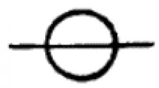
The two-color three-legged LED has some feature, which at first can be confusing, but which can be useful.
We collect the layout from the title picture and examine it. Green wiring refers to the green crystal, orange - to red.
We connect the battery and click the toggle switch.
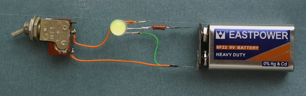
Toggle switch off, green LED
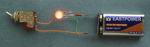
The toggle switch is on, the LED is red (true, red, the photo turned out badly)
With an open circuit, the LED shines green, with a closed ... red. Oh, something is not right! After all, the green crystal is connected directly to the battery and should always shine! Those. when the toggle switch closes, we should get a glow of both crystals and a yellow color! But if you look closely, you can see that when you turn on red, the green goes out! Directly some kind of switch.
So, we will depict the scheme of this ... scheme 🙂
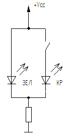
Yeah, okay. Incorrect inclusion of LEDs! After all, all Murzil’s say: with parallel connection, each LED should have its own ballast resistor. And with this scheme, due to individual differences, they will shine differently: someone is brighter, someone is dimmer.
But! We are seeing a different picture. We have one crystal burning. Those. a simple make contact works like a switching contact. Why? Let's try to figure it out. To do this, we assemble a simpler circuit - with one LED, but we hang it with measuring instruments and we will observe their readings:
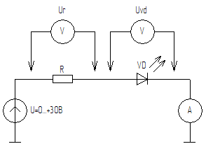
We have:
- adjustable voltage source;
- experimental chain R and VD;
- an ammeter showing current in the circuit;
- voltmeters with which we can measure the voltage separately on R and VD.
We will gradually raise the voltage from 0, observing the readings of the instruments.
With a diode more interesting. The fact is that the diode (including the LED) is a nonlinear element. Its resistance in the forward direction depends on the flowing current. The higher the current, the lower the resistance. In addition, the diode has a so-called. threshold. At a voltage below this threshold, the diode will be closed even in the forward direction.
So, slowly twist our power source, raising the voltage. And immediately we see the difference from the resistor circuit. For half a volt, one volt, and the ammeter does not seem. Current \u003d 0. Voltage Ur \u003d 0, and Uvd \u003d voltage of the source. Those. the diode is closed, its resistance is very high, there is practically no current in the circuit, and all the voltage "drops out" on it.
But here we got to the threshold, for the red LED it is about 1.3 volts. The LED has opened and dimly lit. The ammeter from scratch immediately jumped to a certain value. Also, the stress Ur suddenly appeared.
Add a little more. At a voltage of about 1.7 V, the LED lit up at full strength.
Add further. And again we see strange! Current grows as expected. Ur is growing. But Uvd remains at 1.7 V! Those. the diode “strives” to keep the voltage on itself equal to 1.7 V. For this, with increasing current, it decreases its resistance and the resistor gets more and more voltage - after all, the sum Ur + Uvd must be equal to the voltage of the source.
This will happen until the current rises so much that the diode overheats and burns out. In this case, the difference in brightness between “just lit up” and “almost burned out” will be insignificant although the current has changed many times. And the voltage Uvd increased, but not much, somewhere up to 2.5 V.
The voltage at which the LED "went into mode", i.e. its current and brightness correspond to the norm and are considered a typical voltage drop for this type of semiconductor. Yes, for different types of semiconductors, these values \u200b\u200bare different. The silicon p-n junction will have one value, the germanium p-junction will have a different value, the junction based on arsenide gallium (red LED) will have the third, and the metal-semiconductor junction (Schottky diode) fourth.
And here we can finally answer the question why the scheme from the title of the article works so strangely. The fact is that the green and red crystals are made of different materials having different thresholds and different voltage drops. In my layout, the drop on the green crystal was about 2 V (at a supply voltage of 3 to 9 V), and on the red - 1.7 V.
What happens when parallel to the luminous green we connect red? The voltage immediately drops to 1.7 V! And green just doesn’t have enough direct voltage to open. Everything turned out to be simple 🙂
Now. How can I use this wrong scheme. For example, you can switch from green to red using one leg of the microcontroller, and not two. True, such a solution will require some additional “strapping,” but if you need to tightly save your legs - it may work.
Simpler schemes can also use this trick. One example will be in the next article.