The practice of repairing power inverters for backlight lamps for laptop LCD panels. How to repair or repair LCD and LCD TVs yourself if your inverter breaks down. The main malfunctions of inverters in modern LCD TVs and plasma, as well as
If you are going to exercise self repair monitor, then you should have an idea how to check the inverter or the backlight is to blame.
Check is not so difficult.
To begin with, the diagnosis of surface of.
You have determined that the problem is still with the backlight. We disassemble the monitor, do a visual inspection of the board. If you find bloated electrolytes, then change. Turn on and watch. The backlight never appeared. Then you need to repair the inverter and ensure that the voltage is normal.

There can be many problems: there is no voltage from the power supply, the fuse for powering the inverter has blown, again the capacitors, the output power transistors of the inverter.

Turned on at the end then.
But after a couple of seconds it went out. Or it turned on initially and went out right away. Not the point. The important thing is that now we must visually look at the quality of the backlight. To do this, disconnect the loop from the matrix, which comes from the scaler board. This will provide us with a power off of the matrix itself. Now turn on and look carefully at how the matrix is \u200b\u200billuminated. The task is to see the darkening, redness, in general, everything that will differ from the uniform white glow. If the reddish tint is somewhere - a replacement lamp. If it is noticeable that part of the screen is darkened, then the lamp does not work here.

It is for these reasons that the inverter protection is triggered. When the lamp is defective. However, this is not all. If the lamp does not burn at all, then it is necessary to transfer the connectors on the inverter so that a non-burning lamp should be connected to another channel of the inverter, if the lamp lights up, and the one that was connected instead of the faulty one does not burn, then the matter is most likely in the transformer.
The transformer is one in two lamps, and sometimes one in a lamp. In any case, you need to take a tester to measure the resistance and ring the output windings without lamps. Resistance should differ by a few ohms. If the differences are Ohm in 20-30, then it is worth considering the serviceability of the transformer. If more than 50, then the transformer clearly has problems and should be replaced.
That's all.
If the lamp is faulty, it is problematic to replace it, since it is difficult to find the lamp itself. Many are not taken precisely for this reason. But you can get out of the situation by replacing the lamp with the equivalent load. You need to take a capacitor, at about 300pF and a voltage of 3 kV, and solder it to the output on the board. It should work, the inverter in the protection does not go away, but the dark part of the screen will be. Well, what to do)) At least so.
Difficult? Contact our workshop, we will repair your monitor. Subscribe to our group
Today we’ll talk about how to repair or repair the LCD and LCD TV yourself if his inverter breaks down. Consider the main malfunctions of inverters in modern LCD TVs and plasma, as well as ways to solve them at home
For the operation of the LCD panel, the light source is of paramount importance, the luminous flux of which forms an image on the monitor screen.
To create the luminous flux, cold cathode fluorescent lamps (CCFL) are used, which are located on the edges of the monitor (usually above and below) and with the help of frosted scattering glass uniformly illuminate the entire surface of the LCD matrix.
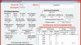
The "ignition" of the lamps, as well as their power in operation, is provided by inverters. The inverter must ensure reliable start-up of lamps with voltages above 1500 V and their stable operation for a long time at operating voltages from 600 to 1000 V. Lamps in LCD panels are connected according to the capacitive circuit (see Fig. A1). The operating point of stable luminescence (RT - on the graph) is located on the line of intersection of the load line with a graph of the dependence of the discharge current on the voltage applied to the lamps. The inverter in the monitor creates the conditions for a controlled glow discharge, and the operating point of the lamps is located on the gentle part of the curve, which allows them to achieve a constant glow for a long time and provide effective brightness control.

The inverter performs the following functions:
* Converts a constant voltage (usually +12 V) into a high-voltage variable;
* stabilizes the current of the lamp and, if necessary, regulates it;
* provides brightness adjustment;
* agrees the output stage of the inverter with the input resistance of the lamps;
* Provides protection against short circuit and overload.

No matter how diverse the market of modern inverters is, the principles of their construction and operation are almost the same, which simplifies their repair.
The unit of standby mode and turning on the inverter is made in this case on the keys Q1, Q2. The LCD panel takes some time to turn on, so the inverter also turns on after 2 ... 3 s after switching the panel to operating mode. ON voltage is supplied from the main board and the inverter enters the operating mode. The same unit provides shutdown of the inverter when the LCD panel switches to one of the energy saving modes. When the positive voltage ON (3 ... 5 V) arrives at the base of transistor Q1, the voltage +12 V goes to the main circuit of the inverter - the brightness control unit and the PWM controller.

The control unit for controlling the brightness of the glow of the lamps and the PWM (3 in Fig. A2) is made according to the scheme of the error amplifier (UO) and the PWM pulse shaper.
It receives the voltage of the dimmer from the main board of the monitor, after which this voltage is compared with the feedback voltage, and then this produces an error signal that controls the frequency of the PWM pulses. These pulses are used to control the DC / DC converter (1 in Fig. A2) and synchronize the operation of the inverter-converter. The pulse amplitude is constant and determined by the supply voltage (+12 V), and their frequency depends on the brightness voltage and the threshold voltage level.
The DC / DC converter (1) provides a constant (high) voltage that is supplied to the oscillator. This generator is turned on and controlled by the pulses of the PWM control unit (3).
Elements are not able to perfectly block the flow of light - the black color on the LCD TV screen is actually not completely black.
Among the shortcomings, it is also necessary to note color distortion and loss of contrast, since the viewing angle of the LCD is not so wide. Because of this feature, LCD TVs could not catch on for a long time, but now, thanks to the efforts of the developers, the distortions have become almost invisible.
The advantages of TVs with a liquid crystal screen include a wide selection of models with various indicators of brightness (from 250 to 1500 cd / m2) and contrast (from 500: 1 to 5,000,000: 1). Due to this, the buyer can purchase a device that optimally combines the required image quality and affordable price. In addition, LCD TVs are lightweight and thin, so they can be placed on the wall.
But the greatest merit of liquid crystal technology is in its mass character. Due to large-scale production, prices for LCD TVs are now lower than for other similar devices.
The inverter output AC voltage level is determined by the parameters of the circuit elements, and its frequency is determined by the brightness control and the characteristics of the backlight. The inverter converter, as a rule, is a self-excited generator. Both single-cycle and push-pull circuits can be used.The protection unit analyzes the level of voltage or current at the inverter output and generates feedback voltages (OS) and overloads that enter the control unit (2) and PWM (3). If the value of one of these voltages (in case of short circuit, overload of the converter, low level supply voltage) exceeds the threshold value, the oscillator stops its work.
As a rule, on the screen, the control unit, PWM and brightness control unit are combined in one chip. The converter is performed on discrete elements with a load in the form of a pulse transformer, the additional winding of which is used to switch the starting voltage.
All the main nodes of the inverters are carried out in the chassis of the SMD components.
There are a large number of modifications of inverters. The use of one type or another is determined by the type of LCD panel used in this monitor, so inverters of the same type can be found in different manufacturers.
EMAC type PLCD2125207A inverter
This inverter is used in LCD panels of Proview, Acer, AOC, BENQ and LG with a screen diagonal of not more than 15 inches. It is built according to a single-channel scheme with a minimum number of elements (Fig. PZ). With an operating voltage of 700 V and a load current of 7 mA with two lamps, the maximum screen brightness is about 250 cd / m2. The starting output voltage of the inverter is 1650 V, the response time of the protection is from 1 to 1.3 s. On the idling the output voltage is 1350 V. The greatest depth of brightness is achieved by changing the control voltage DIM (pin 4 of connector CON1) from 0 (maximum brightness) to 5 V (minimum brightness). The inverter of the SAMPO company is made in the same way.
Voltage +12 V is supplied to the pin. 1 connector CON1 and through fuse F1 - on the pin. 1-3 assembly Q3 (source of field-effect transistor). The step-up DC / DC converter is assembled on the elements Q3-Q5, D1, D2, Q6. In the operating mode, the resistance between the source and drain of the Q3 transistor does not exceed 40 mOhm, while a current of up to 5 A is passed to the load. The converter is controlled by a brightness controller and PWM, which is made on a U1 chip TL5001 (analogous to FP5001) from Feeling Tech. The main element of the controller is a comparator, in which the voltage of the sawtooth generator (vyv. 7) is compared with the voltage of the UO, which in turn is determined by the ratio between the reference voltage of 1 V and the total feedback voltage and brightness (vyv. 4). The frequency of the sawtooth voltage of the internal generator (about 300 kHz) is determined by the value of the resistor R6 (connected to pin 7 U1).
From the output of the comparator (vyv. 1) are pulled PWM pulses, which are fed to the circuit of the DC / DC converter. The controller also provides protection against short circuit and overload. With a short circuit at the inverter output, the voltage on the divider R17 R18 increases, it is rectified and fed to the pin. 4 U1. If the voltage becomes 1.6 V, the controller protection circuit starts. The protection threshold is determined by the value of the resistor R8. Capacitor C8 provides a “soft” start when the inverter starts or after the end of a short circuit. If the short circuit lasts less than 1 s (the time is determined by the capacitance of the capacitor C7), then the normal operation of the inverter continues. Otherwise, the inverter stops working.
For reliable start-up of the converter, the response time of the protection is selected so as to exceed the start and ignition times of the lamps 10 ... 15 times. When the output stage is overloaded, the voltage at the right terminal of the inductor L1 increases, the zener diode D2 starts to pass current, the transistor Q6 opens and the threshold for the protection circuit decreases. The converter is made according to the scheme of a half-bridge generator with self-excitation on transistors Q7, Q8 and transformer PT1. When the ON / OFF voltage (3 V) is received from the main board of the monitor, the transistor Q2 opens and power is supplied to the controller U1 (+12 V on pin 2).
PWM pulses with pin. 1 U1 through the transistors Q3, Q4 enter the gate Q3, thereby starting the DC / DC converter. In turn, power is supplied from it to the oscillator. After that, a high-voltage alternating voltage appears on the secondary winding of the transformer PT1, which is supplied to the backlight. Winding 1-2 PTT acts as a feedback oscillator. While the lamps are not turned on, the output voltage of the converter rises to a start voltage (1650 V), and then the inverter enters the operating mode. If the lamps cannot be ignited (due to a break, "exhaustion"), spontaneous generation failure occurs.
PLCD2125207A inverter malfunctions and how to solve them
The backlight does not turn on. Check the +12 V supply voltage on the pin. 2 U1. If it is not, check fuse F1, transistors Q1, Q2. If the fuse F1 is faulty, before replacing it, check the transistors Q3, Q4, Q5 for a short circuit.
Then check the ENB or ON / OFF signal (pin 3 of the CON1 connector) - its absence may be due to a malfunction of the monitor main board. They check this in the following way: apply a control voltage of 3 ... 5 V to the ON / OFF input from an independent power supply or through a divider from a 12 V source. If the lamps turn on, the main board is faulty, otherwise the inverter.
If there is a supply voltage and a turn-on signal, but the lamps do not light up, then an external inspection of the transformer PT1, capacitors CU, C11 and lamp connectors CON2, CON3 is carried out, the darkened and fused parts are replaced. If at the time of inclusion on the pin. 11 of the PT1 transformer, voltage pulses appear for a short time (the oscilloscope probe is connected in advance through the divider before turning on the monitor), and the lamps do not light, then they check the condition of the lamp contacts and the absence of mechanical damage to them.
The lamps are removed from the seats by first unscrewing the screw that secures their casing to the matrix casing, and, together with the metal casing in which they are installed, are removed uniformly and without distortions. On some monitor models (Acer AL1513 and BENQ), the lamps are L-shaped and cover the LCD panel around the perimeter, and careless actions during dismantling can damage them. If the lamps are damaged or darkened (which indicates a loss of their properties), they are replaced. Lamps can only be replaced with ones that are similar in power and parameters, otherwise - either the inverter will not be able to “ignite” them, or an arc discharge will occur, which will quickly disable the lamps.
The lamps turn on briefly (about 1 second) and turn off immediately
In this case, protection from a short circuit or overload in the secondary circuits of the inverter is most likely triggered. Eliminate the reasons for the protection to operate, check the operability of the transformer PT1, capacitors CU and C11 and the feedback circuit R17, R18, D3. Check the Zener diode D2 and the transistor Q6, as well as the capacitor C8 and the divider R8 R9. If the voltage on the pin. 5 less than 1 V, then replace the capacitor C7 (better - on tantalum). If everyone the above actions do not give a result, replace the U1 chip.
Turning off the lamps can also be associated with a breakdown in the generation of the converter. To diagnose this malfunction, instead of the lamps, an equivalent load is connected to the CON2, CON3 connectors - a resistor of 100 kOhm and a power of at least 10 watts. In series with it include a measuring resistor of 10 ohms. Devices are connected to it and the oscillation frequency is measured, which should be in the range from 54 kHz (at maximum brightness) to 46 kHz (at minimum brightness) and the load current from 6.8 to 7.8 mA. To control the output voltage, connect a voltmeter between the pin. 11 transformer PT1 and the output of the load resistor.
If the measured parameters do not correspond to the nominal, control the magnitude and stability of the supply voltage on the inductor L1, and also check the transistors Q7, Q8, C9. If the screen lights up when the right (according to the diagram) assembly diode D3 from the resistor R5 is disconnected, one of the lamps is faulty. Even with one working lamp, the image brightness is enough for the operator to work comfortably.
The screen flashes periodically and the brightness is unstable
Check the stability of the brightness voltage (DIM) on the contact. 4 connectors CON1 and after the resistor R3, having previously disconnected the feedback (resistor R5). If the control voltage at the connector is unstable, then the monitor main board is malfunctioning (testing is performed on all available monitor operating modes and over the entire brightness range). If the voltage is unstable on the pin. 4 of the controller U1, then check its mode by direct current in accordance with table. P1, while the inverter must be in operating mode. A faulty chip is replaced.
Check the stability and amplitude of the oscillations of its own sawtooth pulse generator (vyv. 7), the signal amplitude should be from 0.7 to 1.3 V, and the frequency - about 300 kHz. If the voltage is unstable, replace R6 or U1.
The instability of the inverter can be associated with the aging of the lamps or their damage (periodic violation of the contact between the supply wires and the terminals of the lamps). To check this, as in the previous case, connect the load equivalent. If at the same time the inverter works stably, then it is necessary to replace the lamps.
After some time (from several seconds to several minutes), the image disappears
The protection circuit does not work properly. Check and, if necessary, replace the capacitor C7, connected to the pin. 5 controllers, control the direct current mode of controller U1 (see previous malfunction). Check the stability of the lamps by measuring the level of the sawtooth pulses at the output of the feedback circuit, on the right anode D3 (range of about 5 V) when setting the average brightness (50 units). If there are "surges" of voltage, check the health of the transformer and capacitors C9, C11. In conclusion, check the stability of the PWM circuit of the controller U1.
SAMPO DIVTL0144-D21 inverter
It is used to power the backlight lamps of 15-inch matrices by SUNGWUN, SAMSUNG, LG-PHILIPS, HITACHI. The operating voltage is 650 V at a load current of 7.5 mA (at maximum brightness) and 4.5 mA at minimum. The starting voltage (“ignition”) is 1900 V, the frequency of the supply voltage of the lamps is 55 kHz (at medium brightness). The level of the brightness adjustment signal is from 0 (maximum) to 5 V (minimum). Protection response time - 1 ... 4 s.
As a controller and PWM, a U201 chip type BA9741 from ROHM (its analogue TL1451) is used. It is a two-channel controller, but in this case only one channel is used.
When the monitor is turned on, the +12 V voltage is supplied to the pin. 1-3 transistor assemblies Q203 (source field-effect transistor). When the monitor is turned on, the inverter ON / OFF start signal (+3 V) comes from the main board and opens the Q201, Q202 transistors. Thus, a voltage of +12 V is applied to the pin. 9 U201 controllers. After that, the internal sawtooth voltage generator begins to work, the frequency of which is determined by the ratings of the elements R204 and C208 connected to the pin. 1 and 2 microcircuits. On vyv. 10 microcircuit PWM pulses appear, which are fed to the gate Q203 through an amplifier on transistors Q205, Q207.
On vyv. 5-8 Q203, a constant voltage is generated, which is supplied to the oscillator (on the elements Q209, Q210, RT201). A sinusoidal voltage with a range of 650 V and a frequency of 55 kHz (at the time of "ignition" of the lamps it reaches 1900 V) is supplied to the backlight from the output of the converter via the CN201, CN202 connectors. On the elements D203, R220, R222, a circuit for generating a protection signal and a soft start has been implemented. At the moment the lamps are turned on, the energy consumption in the primary circuit of the inverter increases and the voltage at the output of the DC / DC converter (Q203, Q205, Q207) increases, the Zener diode D203 starts to conduct current, and part of the voltage from the divider R220 R222 goes to the pin. 11 of the controller, thereby increasing the threshold of the protection circuit during start-up.
The stability and brightness of the glow of the lamps, as well as protection against short circuit is provided by the feedback circuit on the elements D209, D205, R234, D207, C221. Feedback voltage is supplied to the pin. 14 microcircuits (direct input of the error amplifier), and the brightness voltage from the main monitor board (DIM) to the inverse input of the VO (pin 13), determining the frequency of the PWM pulses at the controller output, and hence the level of the output voltage. At minimum brightness (DIM voltage is 5 V), it is 50 kHz, and at maximum brightness (DIM voltage is zero) - 60 kHz.
If the feedback voltage exceeds 1.6 V (pin 14 of the U201 chip), the protection circuit is activated. If the short circuit in the load lasts less than 2 s (this is the charge time of the C207 capacitor from the +2.5 V reference voltage - pin 15 of the microcircuit), the inverter is restored to operability, which ensures reliable lamp start-up. During a long short circuit, the inverter shuts down.
Malfunctions of the inverter DIVTL0144-D21 and methods for their elimination
Lamps are off
Check the presence of +12 V voltage on the pin. 1-3 Q203, fuse F1 working (installed on the main board of the monitor). If the fuse is defective, then before installing a new one, the Q201, Q202 transistors, as well as the capacitors C201.C202, C225, are checked for short circuit.
Check for ON / OFF voltage: when the operating mode is turned on, it should be 3 V, and when it is turned off or in standby mode, it should be zero. If there is no control voltage, check the main board (the microcontroller of the LCD panel controls the inverter). If all of the above voltages are normal, and PWM pulses on pin. 10 there is no V201 chip, check the Zener diodes D203 and D201, the transformer RT201 (can be determined by visual inspection of the darkened or fused housing), capacitors C215, C216 and transistors Q209, Q210.
If there is no short circuit, then the serviceability and rating of the capacitors C205 and C207 are checked. In the event that the above items are OK, replace the U201 controller. Note that the lack of illumination of the backlight can be due to their breakage or mechanical failure.
The lamps turn on and off briefly
If the backlight persists for 2 s, then the feedback circuit is faulty. If when disconnecting from the circuit elements L201 and D207 on the pin. 7 of the U201 chip, PWM pulses appear, either one of the backlight lamps or the feedback circuit is faulty. In this case, check the Zener diode D203, the diodes D205, D209, D207, the capacitors C221, C219, as well as the inductor L202. Control the voltage on the pin. 13 and 14 U201. In operating mode, the voltage at these terminals should be the same (about 1 V - at medium brightness). If the voltage on the pin. 14 significantly lower than on pin. 13, then check the diodes D205, D209 and the lamp for an open. With a sharp increase in voltage on the pin. 14 U201 microcircuits (above 1.6 V) check the elements PT1, L202, C215, C216. If they are working, replace the U201 chip. When replacing it with an analog (TL1451), check the threshold voltage on the pin. 11 (1.6 V) and, if necessary, select the value of the elements C205, R222. By selecting the ratings of the elements R204, C208, the frequency of the sawtooth pulses is set: on pin. 2 chips should be around 200 kHz.
The backlight turns off after a while (from several seconds to several minutes) after turning on the monitor
First, check capacitor C207 and resistor R207. Then check the serviceability of the contacts of the inverter and the backlight, capacitors C215, C216 (replacement), transformer PT201, transistors Q209, Q210. The threshold voltage on the pin is monitored. 16 V201 (2.5 V), if it is underestimated or absent, replace the chip. If the voltage on the pin. 12 above 1.6 V, check capacitor C208, otherwise also replace U201.
Brightness spontaneously changes over the entire range or in individual operating modes of the TV (monitor)
If the malfunction manifests itself only in some resolution modes and in a certain range of brightness changes, then the malfunction is connected to the main board with a memory chip or LCD controller). If the brightness changes spontaneously in all modes, the inverter is faulty. Check the brightness adjustment voltage (on pin 13 U201 - 1.3 V (at medium brightness), but not higher than 1.6 V). In case the voltage at the DIM pin is stable, but at pin. 13 - no, replace the U201 chip. If the voltage on the pin. 14 is unstable or underestimated (less than 0.3 V at minimum brightness), then instead of the lamps, the equivalent load is connected - a resistor of 80 kOhm. If the defect persists, replace the U201 chip. If this replacement does not help, replace the lamps, and also check the serviceability of their contacts. Measure the voltage on the pin. 12 chips U201, in the operating mode it should be about 1.5 V. If it is below this limit, check the elements C209, R208
Note. In inverters of other manufacturers (ЕМАХ, TDK), made according to a similar scheme, but using other components (except the controller): the SI443 chip is replaced by D9435, and 2SC5706 by 2SD2190. The voltage at the terminals of the U201 chip can vary within ± 0.3 V TDK inverter.
This inverter is used in 17-inch monitors and TVs with SAMSUNG matrices, and its simplified version (Fig. A6) is used in 15-inch LG monitors with LG-PHILIPS matrix.
The circuit is implemented on the basis of a 2-channel PWM controller of the OZ960 O2MICRO company with 4 control signal outputs. As power switches, transistor assemblies of the FDS4435 type (two field-effect transistors with a p-channel) and FDS4410 (two field-effect transistors with an n-channel) are used. The circuit allows you to connect 4 lamps, which provides increased brightness of the LCD panel backlight.
The inverter has the following characteristics:
supply voltage - 12 V;
the rated current in the load of each channel is 8 mA;
lamp operating voltage - 850 V,
starting voltage - 1300 V;
frequency of the output voltage - from 30 kHz (at minimum brightness) to 60 kHz (at maximum brightness).
The maximum brightness of the screen with this inverter is 350 cd / m2; protection response time - 1 ... 2 s.
When the monitor is turned on, +12 V voltage is supplied to the inverter connector - to power the Q904-Q908 keys and +6 V - to power the U901 controller (
In this case, the inverter is in standby mode. The enable voltage of the ENV controller is supplied to the pin. 3 microcircuits from the microcontroller of the main monitor board. The PWM controller has two identical outputs for powering two channels of the inverter: pin. 11, 12 and vyv. 19, 20 (Fig. A5 and A6). The frequency of the generator and PWM are determined by the values \u200b\u200bof the resistor R908 and capacitor C912 connected to the pin. 17 and 18 microcircuits (Fig. A5). The resistor divider R908 R909 determines the initial threshold of the sawtooth voltage generator (0.3 V). On the capacitor C906 (pin 7 U901), the threshold voltage of the comparator and the protection circuit is formed, the response time of which is determined by the value of the capacitor C902 (pin 1).
The voltage of protection against short circuit and overload (when the backlight is broken) goes to the pin. 2 microcircuits. The U901 controller has built-in soft start circuitry and an internal stabilizer. The start of the soft start circuit is determined by the voltage on the pin. 4 (5 V) controllers. The DC-DC to high-voltage lamp supply voltage converter is made on two pairs of p-type transistor assemblies FDS4435 and n-type FDS4410 and is forcedly triggered by PWM pulses. A pulsating current flows in the primary winding of the transformer, and the supply voltage of the backlight lamps connected to the J904-J906 connectors appears on the secondary windings of the T901. To stabilize the inverter output voltages, feedback voltage is supplied through half-wave rectifiers Q911-Q914 and the integrating circuit R938 С907 С908 and is supplied to the output in the form of sawtooth pulses. 9 U901 controller.
When one of the backlight lamps breaks, the current increases through the divider R930 R932 or R931 R933, and then the rectified voltage is applied to the pin. 2 controllers, exceeding the set threshold. Thus, the formation of PWM pulses on the pin. 11, 12 and 19, 20 U901 is blocked. With a short circuit in the circuits C933 C934 T901 (winding 5-4) and C930 C931 T901 (winding 1-8) there are “surges" of voltage, which are rectified Q907-Q910 and also come to the pin. 2 controllers - in this case protection is activated and the inverter shuts down. If the short circuit time does not exceed the charge time of the capacitor C902, then the inverter continues to operate in normal mode.
The fundamental difference between the schemes in Fig. P5 and P6 in the fact that in the first case a more complex “soft” start circuit is applied (the signal is fed to pin 4 of the microcircuit) on transistors Q902, Q903. In the diagram in fig. P6 it is implemented on the capacitor CU. It also uses assemblies of field-effect transistors U2, U3 (p- and p-type), which simplifies their power coordination and ensures high reliability in circuits with two lamps. In the diagram in fig. P5 applies field-effect transistors Q904-Q907, connected by a bridge circuit, which increases the output power of the circuit and the reliability of operation in startup modes and at high currents.
Inverter malfunctions and solutions
Lamps do not turn on
Check for +12 and +6 V supply voltage per pin. Vinv, Vdd of the inverter connector, respectively (Fig. A5). If they are absent, the health of the main monitor board, assemblies Q904, Q905, zener diodes Q903-Q906 and capacitor C901 are checked.
Check the input voltage of the inverter +5 V to pin. Ven when putting the monitor into working mode. You can check the health of the inverter using an external power source, applying a voltage of 5 V to the pin. 3 chips U901. If the lamps turn on, the cause of the malfunction is in the main board. Otherwise, the elements of the inverter are checked, and the presence of PWM signals on the pin is monitored. 11, 12 and 19, 20 U901 and, if they are absent, replace this chip. Also check the serviceability of the windings of the transformer T901 for open and short circuit turns. If a short circuit is detected in the secondary circuits of the transformer, first of all, the health of the capacitors C931, C930, C933 and C934 is checked. If these capacitors are serviceable (you can simply unsolder them from the circuit), and a short circuit occurs, open the lamp installation site and check their contacts. Burned contacts are restored.
The backlight flashes for a short time and immediately goes out
Check the health of all lamps, as well as their connection circuit with the J903-J906 connectors. You can check the health of this circuit without disassembling the lamp unit. To do this, turn off the feedback circuit for a short time, sequentially soldering the diodes D911, D913. If at the same time the second pair of lamps turns on, then one of the lamps of the first pair is faulty. Otherwise, the PWM controller is defective or all the lamps are damaged. It is also possible to check the inverter’s performance by using an equivalent load instead of lamps — a 100 kΩ resistor connected between the terminals. 1, 2 connectors J903, J906. If in this case the inverter does not work and there are no PWM pulses on the pin. 19, 20 and 11, 12 U901, then check the voltage level on the pin. 9 and 10 microcircuits (1.24 and 1.33 V, respectively. In the absence of the indicated voltages, the elements C907, C908, D901 and R910 are checked. Before replacing the controller microcircuit, the ratings and condition of the capacitors C902, C904 and C906 are checked.
The inverter switches off spontaneously after a while (from several seconds to several minutes)
Check the voltage on the pin. 1 (about 0 V) \u200b\u200band 2 (0.85 V) U901 in operating mode, if necessary, change the capacitor C902. With a significant difference in voltage on the pin. 2 from the nominal check the elements in the circuit for protection against short circuit and overload (D907-D910, C930-C935, R930-R933) and, if they are working, replace the controller chip. Check the voltage ratio on the pin. 9 and 10 chips: on pin. 9 voltage should be lower. If this is not the case, check the capacitive divider C907 C908 and the feedback elements D911-D914, R938. Most often, the cause of such a malfunction is caused by a defect in the capacitor C902.
The inverter is unstable, the backlight flashes
The inverter is checked for operability in all monitor operation modes and in the entire brightness range. If instability is observed only in some modes, then the monitor main board is malfunctioning (luminance voltage generation circuit). As in the previous case, the equivalent load is turned on and a milliammeter is installed in the circuit break. If the current is stable and equal to 7.5 mA (at minimum brightness) and 8.5 mA (at maximum brightness), then the backlight is defective and must be replaced. Also check the elements of the secondary circuit: T901, C930-C934. Then check the stability of the rectangular pulses (average frequency - 45 kHz) on the pin. 11, 12 and 19, 20 of the U901 chip. The constant component on them should be 2.7 V at the P-outputs and 2.5 V at the N-outputs). Check the stability of the sawtooth voltage on the pin. 17 chips and, if necessary, replace C912, R908.
SAMPO inverter
It is used in 17-inch SAMSUNG, AOC panels with SANYO matrices, in the Preview SH 770 and MAG HD772 monitors. There are several modifications to this circuit. The inverter generates an output voltage of 810 V at a rated current through each of the four fluorescent lamps (about 6.8 mA). The starting output voltage of the circuit is 1750 V. The frequency of the converter at an average brightness of 57 kHz, while achieving a monitor screen brightness of up to 300 cd / m2. The response time of the inverter protection circuit is from 0.4 to 1 s.
The inverter is based on the TL1451AC microcircuit (analogs - TI1451, BA9741). The microchip has two control channels, which makes it possible to realize a power supply circuit for four lamps.
When the monitor is turned on, the voltage +12 V is supplied to the inputs of the voltage converters +12 V (sources of field-effect transistors Q203, Q204). The voltage for adjusting the brightness of the DIM is supplied to the pin. 4 and 13 microcircuits (inverse inputs of error amplifiers). Upon receipt of an on-voltage of 3 V from the main board of the monitor (pin ON / OFF), transistors Q201 and Q202 open and on the pin. 9 (VCC) of the U201 chip, a voltage of +12 V. is applied. 7 and 10, rectangular PWM pulses appear, which enter the bases of transistors Q205, Q207 (Q206, Q208), and from them to Q203 (Q204).
As a result, voltages appear on the right-side outputs of the chokes L201 and L202, the value of which depends on the duty cycle of the PWM signals. These voltages feed the circuits of oscillators made on transistors Q209, Q210 (Q211, Q212). On the primary windings 2-5 transformers PT201 and RT202, respectively, a pulse voltage appears, the frequency of which is determined by the capacitance of capacitors C213, C214, the inductance of the windings of 2-5 transformers PT201, PT202, as well as the level of the supply voltage. When adjusting the brightness, the voltage at the outputs of the converters and, as a consequence, the frequency of the generators changes. The amplitude of the output pulses of the inverter is determined by the supply voltage and the state of the load.
The self-oscillators are made according to a half-bridge circuit, which provides protection against high currents in the load and an open circuit in the secondary circuit (turning off the lamps, open circuit of capacitors C215-C218). The basis of the protection circuit is in the U201 controller. In addition, the protection circuit includes elements D203, R220. R222 (D204, R221, R223), as well as the feedback circuit D205 D207 R240 C221 (D206 D208 R241 C222). When the voltage at the converter output increases, the Zener diode D203 (D204) breaks through and the voltage from the divider R220, R222 (R221, R223) is fed to the input of the overload protection circuit of the controller U201 (pin 6 and 11), increasing the protection threshold for the lamp start-up time.
The feedback circuits rectify the voltage at the output of the lamps and it goes to the direct inputs of the error amplifiers of the controller (vyv. 3, 13), where it is compared with the brightness adjustment voltage. As a result, the frequency of the PWM pulses changes and the brightness of the lamp glow is maintained at a constant level. If this voltage exceeds 1.6 V, then a short circuit protection circuit will start, which will work during the charging time of the capacitor C207 (about 1 s). If the short circuit lasts less than this time, then the inverter will continue normal operation.
SAMPO inverter malfunctions and solutions
Inverter does not turn on, lamps do not light
Check for the presence of +12 V and the active state of the ON / OFF signal. In the absence of +12 V, check its presence on the main board, as well as the health of transistors Q201, Q202, Q205, Q207, Q206, Q208) and Q203, Q204. If there is no ONN / OFF inverter turn-on voltage, it is supplied from an external source: +3 ... 5 V through a 1 kΩ resistor to the base of Q201 transistor. If at the same time the lamps turn on, then the malfunction is associated with the formation of the inverter switching voltage on the main board. Otherwise, check the voltage on the pin. 7 and 10 U201. It should be equal to 3.8 V. If the voltage at these terminals is 12 V, then the U201 controller is faulty and must be replaced. Check the voltage reference on the pin. 16 U201 (2.5 V). If it is zero, check the capacitors C206, C205 and, if they are working, replace the controller U201.
Check for generation on pin. 1 (sawtooth voltage with a scale of 1 V) and, in the absence thereof, capacitor C208 and resistor R204.
The lamps light up, but immediately go out (within a period of time less than 1s)
Check the health of the Zener diodes D201, D202 and transistors Q209, Q210 (Q211, Q212). In this case, one of the pairs of transistors may be faulty. Check the overload protection circuit and the health of the Zener diodes D203, D204, as well as the ratings of resistors R220, R222 (R221, R223) and capacitors C205, C206. Check the voltage on the pin. 6 (11) controller chips (2.3 V). If it is underestimated or equal to zero, check the elements C205, R222 (C206, R223). In the absence of PWM signals on pin. 7 and 10 of the U201 chip measure the voltage on the pin. 3 (14). It should be 0.1 ... 0.2 V more than the pin. 4 (13), or the same. If this condition is not met, check the elements D206, D208, R241. When carrying out the above measurements, it is better to use an oscilloscope. The inverter shutdown may be caused by a break or mechanical damage to one of the lamps. To verify this assumption (so as not to disassemble the lamp assembly), the +12 V voltage of one of the channels is turned off. If at the same time the monitor screen starts to glow, then the malfunctioning channel is faulty. They also check the health of transformers RT201, RT202 and capacitors C215-C218.
The lamps turn off spontaneously after a while (from units of seconds to minutes)
As in previous cases, check the elements of the protection circuit: capacitors C205, C206, resistors R222, R223, as well as the voltage level on the pin. 6 and 11 chips U201. In most cases, the cause of the defect is caused by a malfunction of the capacitor C207 (determining the response time of the protection) or the controller U201. Measure the voltage at the chokes L201, L202. If the voltage rises steadily during the duty cycle, check transistors Q209, Q210 (Q211, Q212) capacitors C213, C214 and zener diodes D203, D204.
The screen flashes periodically and the brightness of the backlight is unstable
Check the health of the feedback circuit and the operation of the error amplifier of the U201 controller. Measure the voltage on the pin. 3, 4, 12, 13 microcircuits. If the voltage at these terminals is lower than 0.7 V, and on the pin. 16 below 2.5V then replace the controller. Check the health of the elements in the feedback circuit: diodes D205, D207 and D206, D208. Connect 120 kΩ load resistors to the CON201-CON204 connectors, check the level and stability of the voltage on the pin. 14 (13), 3 (4), 6 (11). If the inverter operates stably when the load resistors are connected, replace the backlight.
In this article, the author continues the topic that began in the article - describes in detail the diagnostics of power inverters for cold cathode electroluminescent backlight lamps (CCFL lamps). Schematic diagrams of all inverters considered in the article are given in.
Correct fault diagnosis significantly reduces repair time and costs. The main problem that occurs when diagnosing a backlight system is to determine what is wrong: a backlight or an inverter. Practice shows that the malfunction of CCFL lamps is manifested as follows:
The screen is painted in red;
When you turn on the laptop, the screen color has a red tint, and then gradually becomes normal;
The backlight of the panel (the whole image) blinks in time with the change in the brightness of the plot;
The panel backlight starts flashing, and then turns off.
The malfunction of the lamps with such manifestations is confirmed in about half of the cases, in other cases it is necessary to refer to the methods described below.
Structurally, the inverter board and the backlight are usually located under the front cover of the laptop screen. The first thing we are convinced of: are the backlight problems related to the malfunctions of the laptop motherboard. If there is an image when connecting external display devices - a monitor, a TV, a projector, then most likely the laptop backlight system is faulty.
To repair an inverter or backlight system, it is necessary to have at the workplace the minimum necessary measuring equipment - a multimeter, an oscilloscope and an autonomous power supply with an adjustable constant voltage from 1.5 to 30 V with current protection (1 A), as well as a working CCFL lamp.
To eliminate the influence of a faulty lamp when repairing the inverter, an equivalent load is used. It is preferable to connect a well-functioning lamp to the tested inverter. If there is none, then a resistor of 100 ... 130 kOhm with a power of 2 ... 5 W is connected to the inverter output connector (as recommended by inverter manufacturers). The resistor is selected based on the required secondary voltage at the feedback output. As an equivalent load, a ceramic capacitor with a capacity of 20 ... 200 pF and an operating voltage of at least 2 kV can also be used. The use of a capacitor in the study of the inverter in the operating mode is preferable, however, problems may occur when starting the inverter controller. The inverter can be considered serviceable if there is a stable sinusoidal voltage at the load equivalent.
Replacing the lamp requires special care and ensuring the cleanliness of the room. Work is carried out with gloves. In some cases, when a complete disassembly of the matrix is \u200b\u200brequired, this operation is carried out in "clean" rooms and in overalls.
Illumination malfunctions are sometimes associated with a violation of the contact at the place of welding (soldering) of the inverter wire and the lamp electrode. In this case, it is possible to restore the backlight system. To do this, you must have an insulating tube (rubber tip) from a faulty CCFL lamp. Welding or soldering is best done with brazing material and a gas soldering iron, which creates a high temperature at the place of soldering. The tube pre-worn on the wire is gently pulled to the soldering place and the lamp is ready for operation.
Faults and repair of the SAMSUNG laptop inverter
To access the inverter board and the lamp, remove the decorative cover from the laptop LCD panel, disconnect the cable connecting it to the motherboard and the lamp cable from the inverter.
The screen does not light
Check the health of the inverter elements by external inspection. In this case, the malfunction of the power elements and, first of all, the transformer is determined by the darkening of its body, charred insulation, darkening and even destruction of the board under it.
Check the voltage at the CN1 connector (Fig. 3 c): +12 V at pins 1-2, the inverter shutdown voltage at pin 4 and the brightness voltage at pin 3.
In normal mode, when loading the video card drivers, the voltage on pin 4 of CN1 should be absent. The inverter turns on automatically when power is applied. The brightness voltage (pin 3) must be at least 0.5 ... 2 V.
Check the voltage at the emitter of transistor Q4, and in case of its absence, check fuses F1, TF1, as well as transistors Q7 and Q5.
Check the health of transistors Q1, Q2. These are digital transistors of the type KST1623, they are available in the L4 package, they can be replaced with an analog of the type BSS67R. If transistor Q1 fails, just replace it. If the transistor Q2 fails, the health of the transistor Q7 and the operational amplifier U1A are checked.
If fuse F1 is serviceable, and TF1 (self-healing fuse) is defective, then before replacing it, check the health of transistor Q4 and zener diode D2.
Check the brightness adjustment voltage at pin 3 of CN1. For diagnostics, a voltage of about 3 V from an external source is applied to pin 3. If the screen lights up, then the cause of the malfunction is in the laptop motherboard. In this case, you can forcibly turn on the screen backlight by applying voltage from a resistor divider (80 kOhm in the upper arm (to +5 V), and 40 kOhm in the lower arm) connected to the +5 V bus. If the screen does not light up, check the Q8 transistor .
The backlight turns off after 1-2 seconds after the start of loading the operating system
First of all, the health of CCFL lamps is checked. Connect the oscilloscope to pin 1 of the CN2 connector (see Fig. 3 c) and the equivalent load. If there is a sinusoidal voltage with an amplitude of 500 ... 700 V and a frequency of 60 ... 70 kHz on this ("hot") contact of the CN1 connector, then the inverter is working and the backlight can be turned off due to a lamp malfunction or a contact failure between the inverter wire and the electrode lamps. All this requires disassembling the laptop and dismantling the lamp. Observe the shape and voltage level at the equivalent load for at least 10 minutes, the faulty lamp is changed. If there is no voltage or its shape has significant distortions, then the malfunction is associated with internal malfunctions in the inverter.
Check the feedback loop. If, when the inverter is turned on, a signal is recorded on the “cold” lamp contact with an oscilloscope, its signal (its shape does not matter) with an amplitude of at least 1.5 V, and at pin. 6 U1 voltage remains unchanged (constant voltage, which is measured with a multimeter), check the health of the diode assemblies D4, D5 (they can be replaced with any suitable in size, or two separate diodes like BAV99 in SMD-cases). If the assemblies D4, D5 and the resistor R14 (1 kOhm) are operational, then the U1 chip is faulty.
Check the precision stabilizer U2 (TL341). If it is working, then on pin. 5 U1 must be a constant voltage of 1.5 V. In addition, this inverter protection line is connected with brightness control and overload protection circuit. To determine which of these circuits is faulty, they are sequentially (but not simultaneously) disconnected for a while. First, the protection circuit D3 R3 R4 is turned off, then the brightness control circuit is transistor Q8. If the lamps work stably when these circuits are turned off, then there is a malfunction in these circuits.
Check for a contact in the CN2 connector. In the case of a visible burning contact is restored. If the contact is not suspicious, an equivalent load is connected. Check the D3 C3 C4 D5 overload protection signal conditioning circuit. Protection can be triggered due to overheating of transformer T1, malfunction (leakage) of transistors Q5, Q6.
Faults and repair of the inverter based on the MP1101 controller
The screen does not light
Check for voltage at pins 4 (VCC), 2 (Enable) of the JP1 connector (Fig. 4 c). At the same time, the supply voltage should be 12 V, the enable voltage of the inverter Enable is at least 1.5 V. The absence of the Enable voltage indicates a malfunction of the laptop motherboard, most likely the video card. The absence of 12 V voltage on the JP1 connector when the cable connecting the inverter to the motherboard is disconnected indicates a malfunction of the motherboard. If a voltage of 12 V is present on the connector, and on the pin. 6 U1 it is equal to zero, then check the health of the filtering capacitors, fuse F1 and controller U1.
Check the voltage of the inverter on the pin. 4 U1. If it is missing, check its presence on the contact of the connector disconnected from the inverter board. If there is no voltage, check the laptop circuit. The absence of the inverter turn-on voltage can be due to either fault U1 or an open or cold soldering of the REN1 resistor (there are no radio element designations on the inverter board based on the MP1011 controller, therefore they are oriented in Fig. 4 c). To fix this malfunction, simply solder the SMD resistor REN1. Check the health of transformer T1 (see above), connector CON2 and wires.
The backlight turns on for 1-2 seconds and turns off
First of all, check the elements of the feedback circuit D2 (a, b) CSENSE RSENSE. Diodes are checked for breakage or breakdown. Check the health of the lamp (see above). Connect the equivalent load. Connect the oscilloscope to the Lamp + circuit (Fig. 4 c). If after starting the loading of the operating system, a sinusoidal voltage of 500 ... 700 V is present on this pin, then the inverter main board is operational and a lamp replacement is necessary.
The reason for the disappearance of the backlight may be the malfunction of the feedback node. If when you turn on the screen on the pin. 2 for a while a positive voltage of about 0.5 V appears, but the lamps go out, then the MP1011 controller should be replaced. If the feedback voltage is less than 0.1 V, check all the elements in the feedback circuit: D2, RSENSE, CSENSE.
If, when the inverter is turned on, a signal with an amplitude of more than 0.5 V is detected on the “cold” output of the lamp with an oscilloscope, and on the pin. 2 U1 voltage remains unchanged (constant voltage, which can be measured with a multimeter), then check the health of the diode assembly D2, it can be replaced by two diodes of the type BAV99. If the diodes are working and the RSENSE resistor (140 Ohms) is not disconnected (cold soldering), then the MP1011 controller is faulty.
The backlight turns off after a few seconds or minutes
In this case, check the T1 transformer, the CSER capacitor (for leakage) and the lamp connection wires for a possible violation of insulation and touching metal objects of the case.
Faulty inverters based on the OZ9938 controller
The screen does not light
Check the health of fuse F1 (Fig. 5 c). If it is faulty, then before replacing it, check the health of the T1 transformer according to external signs (darkening, burnt insulation, burn-through of the board). Then check the breakdown of the transistor assembly of field-effect transistors U1. If the OZ9938 controller is powered by a separate parametric stabilizer (not shown in the diagram), the health of its elements is checked.
If the inverter circuit is serviceable and at terminal 7 of the T1 transformer there is a sinusoidal voltage of 550 V at a frequency of 55 kHz, then the condition of the SJ connector is checked.
Check for a turn-on voltage (at least 1 V) on track 6 of CN2. If the voltage is below normal, solder the pin. 10 controllers from the ENA bus. If the voltage at pin 6 increases to 2 V, check capacitor C18 or replace controller U2. If the voltage on pin 6 remains low - the reason is the laptop motherboard. You can exit the situation by applying a voltage of 2 V from an external source.
Check the voltage on the pin. 4 U2, if it is less than 0.1 V, then check the controller, laptop board and capacitor C10. Check the voltage on the pin. 11 U2, which in normal mode should be more than 3 V, with a reduced voltage on this pin, check C14, solder the resistor R9. If these items are OK, then replace the controller. The backlight turns on for 1-2 seconds and turns off
This defect may be due to a lamp malfunction and its connection circuit. If the lamp is working, then check the feedback circuit D1 C22. If, in the absence of an inverter enable signal, the voltage at terminal 6 U2 is more than 1 V, then this microcircuit is faulty and is replaced. If the voltage on the pin. 6 less than 0.7 V, the lamp is working, and the backlight turns off for several seconds, check the overload protection circuit D2 R5 R3. If the voltage on the pin. 6, when the inverter is turned on, it increases and at one point it exceeds 3 V and the lamps turn off, the reason is the overload of the inverter output stage. This may be due to a lamp malfunction (problems associated with starting when the lamp is delayed to start). In addition, overload can be associated primarily due to the presence of short-circuited turns of the transformer windings.
If the voltage on the pin. 6 does not exceed 3 V, but the lamp turns off, then check for a voltage of not more than 3 V per pin. 7 U2. If the voltage is below this level, then check the capacitor C8 (leakage) or replace the controller U2.
The backlight turns off a few minutes after turning on
Check the overload protection circuit D2 C2 C5. Check the health of the transformer T1 (see above). Sometimes a malfunction manifests itself after some time, during which the transformer is heated (above 50 ° C), then it is necessary to replace it. Check the health of the transistor assembly U1 (can be determined by its operating temperature). As a rule, this malfunction disappears during the “freezing” of suspicious elements by Freeze gel. If the time after which the backlight turns off is unstable, then check the health of the lamp and its connector.
Faulty inverters based on the OZ960 controller
The screen does not light
For inverters of the AMBIT and KUBNKM type (see Fig. 6 c), this may be accompanied by a lack of indication on the front panel. In this case, the laptop is disassembled and the presence of +12 V voltage is checked (for KUBNKM inverters, the input connector J1 (CN1) is 20-pin, the voltage is supplied to the 4 extreme contacts, and for AMBIT inverters the connector is 16-pin, and the power voltage is supplied to the 2 extreme contact). If the fuse F1 is faulty, check the transistor assemblies U1, U3. Check the presence of supply voltage on the pin. 5 OZ960 (U2) controllers. This voltage, in contrast to the typical inverter circuit (Fig. 6 c), comes from pin 1 J1 through the stabilizer on transistor Q1 (designation on the board). In AMBIT inverters, the U2 controller is powered by pin 4 of J1. The power supply voltage on the connector itself may be absent due to a malfunction of the laptop power supply unit or due to a short circuit to ground on the pin. 5 U2. For diagnostics, disconnect the SVDC line from connector J1 and, if a voltage appears on the bus, the inverter is faulty.
Check the presence of the enable voltage of the ENA controller on the pin. 3 U2, it must be at least 2 V. In the KUBNKM inverter, the on-voltage of the controller comes from transistor Q1 (its power supply is removed from it) but through the resistor 10 kOhm. Other modifications of inverters based on the OZ960 controller may also have their own characteristics and differences from the typical circuit, but the troubleshooting procedure in them is the same.
If the LEDs on the laptop keyboard panel are lit, there is no screen backlight, and the voltages listed above are present, then the condition of the assemblies of field-effect transistors U1, U3, as well as zener diodes D1, D2 (4.7 V) is checked.
When you turn on the laptop, the presence of rectangular pulses on the pin is monitored by an oscilloscope. 11-12 and 19-20 U2. If there are no pulses and the assemblies U1, U3 are working, then check for the presence of voltage 2.5 V pin. 7 U2. If it is not there or it is underestimated, check C13 and replace the controller. Check for the presence of a sinusoidal signal on the pin. 18 U2 with a frequency of 50.60 kHz. If the frequency is significantly different from the nominal or there is no signal at all, check the elements C5, R4.
The lack of backlight may be due to the absence of (underestimated) voltage on the pin. 14 controllers. If the voltage at this terminal is less than 1 V, a voltage of 3 V is supplied from an external source. If the screen lights up at the same time, then the problem is connected with the voltage supply of the brightness control from the laptop board. In this case, you can apply voltage from pin 1 J1 to the brightness control input through a resistive divider, but keep in mind that the brightness will not be regulated
The backlight turns off after 1-2 seconds after turning on the laptop
Verify that the backlight is in good condition (see verification method above). The oscilloscope is connected to the "hot" (upper according to the diagram in Fig. 6 c) terminal of transformer T1. If, when you turn on the laptop, a sinusoidal voltage of 55 ... 60 kHz appears on this pin and immediately disappears, the T1 transformer is working. Then, the transistor assemblies U1, U2 are checked for leakage: they measure the resistance between the source and the drain with an ohmmeter, and if it shows a final value of 100 kOhm, the assembly is replaced. Check the health of the capacitor C4 for leakage (ESR).
Check for the presence of feedback voltage on the pin. 8 of the controller, it must exceed 1.25 V. If the voltage is below this value, check the diode assembly CR1, and also solder the resistor R8. If there is no result, replace the U2 controller.
The backlight turns off after a few seconds or minutes
In this case, check the surge protection circuit. Disconnect it from the main circuit (just solder the diode assembly CR2). When you turn on the laptop, check for voltage on the pin. 2 controllers (should be no more than 1 V). If this voltage exceeds the specified level, check the threshold value of 2.5 V pin. 7. If it is not there or the voltage is too low, replace the controller. If the voltage on the pin. 2 is normal, and when the protection circuit is connected, the voltage becomes higher than 2 V or changes with time, check the health of the transformer, capacitors C7, C11, diode assembly CR2. You can replace the transformer with any type from another inverter (this circuit is insensitive to the type of transformer), the only thing that will need to be adjusted is the feedback voltage coming from the cold end of the lamp (by selecting resistor R8).
In an AMBIT type inverter, in which the OZ979 chip is used to power the keyboard LEDs, you can try to restore the screen backlight according to a temporary pattern. They turn off the lamps and on the back side of the LCD matrix fix (stick) the LED lines on the top and bottom of the screen with a calculation of 3 pcs. in 5 lines, the first LED is connected to pin 3 of OZ979, and the last is connected to the housing. This method is suitable for small screens of 10-12 inches.
You can use the inverter circuit based on OZ960, after the transformer instead of the capacitor C4 they put a double diode in the SMD case and a quenching resistor with a nominal value of 50 Ohms. Resistance is more accurately selected when installing LEDs to ensure normal illumination and, depending on their operating current, 16 super-bright LEDs are enough for a normal illumination of a 15-inch display, for example, FYLS-1206W with a white glow. LEDs can be glued to the fluoroplastic tape and connect them with thin conductors. In this case, the input voltage on the first LED should not exceed 80 V at a current of 25-50 mA. The current through the LEDs is set by selecting the rating of the limiting resistor.
Some circuits based on the OZ960 differ from the typical, including the name and location of some electronic components.
Sometimes there is a decrease in the brightness of the backlight and its adjustment is not enough. This is due to a decrease in the discharge lamp current due to an increase in the transition resistance at the contact point on the circuit board of the high-voltage winding of transformer T1 and ballast capacitor C4. The problem is fixed by soldering the capacitor leads.
Literature
1. Vladimir Petrov. Repair and maintenance of power inverters for backlight LCD laptop panels. Repair & Service, 2010, No. 3, p. 37-40.
For a good image on an LCD TV, the matrix must have good lighting. In LCD TVs, the backlight is provided by a voltage inverter made on lamps, LEDs or the more advanced OLED (based on organic LEDs) backlight. The backlight should provide uniform illumination of the entire surface of the matrix, sufficient brightness, a quick response to changes in signal brightness.
The most common symptom of an inverter malfunction is the lack of image in the presence of sound. Although another option is possible, when the TV tries to turn on, it again goes into standby mode and the sound does not appear.
It is impossible to describe all the possible malfunctions of inverters, so in this article I will give the main ones, understanding the essence of which you can repair the voltage inverters of LCD TVs with your own hands.
Here are some signs of inverter malfunction:
- The backlight does not turn on;
- The backlight turns on and off;
- It does not turn on after a long period of inactivity;
- Flashing screen brightness;
- Uneven screen brightness.
But first, let's figure out their device.

4-lamp LCD TV inverter board
The inverter device can be conditionally divided into functional blocks, from here it will become clear that they are all similar to each other.
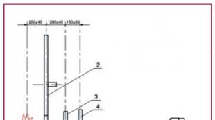
Given below circuit diagram The inverter belongs to the lamp backlight. The lamps are connected according to a capacitive circuit, which ensures the constancy of their luminescence over time and provides effective brightness control. Transistors Q1, Q2 - turn on and turn on the inverter.

Inverter circuit diagram
Block (1) provides a constant voltage generator with keys ((4) usually consists of two field-effect transistors, for example APM4010 and APM4015), which is turned on and controlled by PWM signals. The brightness control unit (2) and PWM (3) are usually constructed in a single chip. A pulse-width modulator (PWM) controls the load in the secondary circuits and if the lamps fail, it does not allow the oscillator 4 to turn on, which will save the keys or transformer from failure.
The necessary luminous flux is created by cold cathode fluorescent lamps (R) (CCFL) located behind the matrix and uniformly illuminate it.
PRINCIPLE OF OPERATION
The inverter must provide several functions:
- Change direct voltage to high voltage alternating current;
- Provide brightness adjustment;
- Stabilize the current of lamps and regulate it;
- Provide protection against short circuit and overload.
The matrix backlight inverter (for lamps) should provide a voltage of usually 600 volts with a load current of approximately 10 mA and provide a maximum screen brightness of about 250 cd / m2. In this case, the initial output voltage will be about 1600 V, and the response time of the protection will be from 1 to 1.3 s. For a confident start, the protection response time is selected 10 times more than the start time.
When voltage is supplied from the power supply, a signal (usually 3-5 volts) to exit the standby mode is received approximately 2 seconds after the TV is turned on from the main board and the backlight inverter goes into operation.
The inverter controller of the TV provides a “soft” start when the inverter is started, as well as protection against short circuit and overload. If the short circuit lasts less than 1 s, then the inverter will continue to operate, otherwise it will turn off.
PWM pulses go to the converter, usually made according to the scheme of a semi-bridge generator with self-excitation, and start the DC / DC converter and the voltage for the backlight appears on the secondary side of the inverter transformer.
A small winding performs a feedback function in the inverter circuit of the TV.
When the lamps are “ignited” at the beginning of operation, the voltage of the converter rises to 1600 V, and only then the inverter enters the operating mode. A faulty lamp, a capacitor in the secondary circuit or a short circuit of the secondary winding leads to a breakdown of generation.
The inverter voltage of an LCD TV is usually 24 or 48 volts (for a large diagonal). The backlight of a laptop is usually powered by a voltage of 18 - 19 volts.

The board of such an inverter is small and located at the bottom of the screen. In this case, the U2 controller OZ9938 controls the keys U1 AM4428 contact CN1 goes to the lamp. Power is supplied through the VIN pins, minus GND, brightness control and inclusion on the DIM and ENA pins.

INVERTER FOR LCD
In principle, there is no particular difference other than a change in voltage. For example, an inverter LCD TV is more often used voltage of 12 volts. The output can vary from 60 to 100 volts mainly. This variation depends on the diagonal of the TV and, accordingly, the number of LEDs used for backlighting.
REPAIRS
Anyone who knows a little about electronics and works with a soldering iron and a multimeter can repair the inverter with his own hands, since there is nothing extraordinary in it.
For breakdowns, I probably must say, there are no major ones, everything breaks. Lamps, keys, transformers, controllers burn out.
Most often, the backlight inverter fails due to breakdowns of electrolytic capacitors in the power supply and power filters of the inverter itself. Losing capacity, swelling and closing the power circuit, they lower the voltage. Keys begin to work with greater overload and burn out.
In LCD TVs, the diodes themselves often burn. When repairing a TV, you can replace the entire tape with LEDs or check each one and replace it individually. For example, you have 3 stripes on your TV led strip 7 diodes each. It is known that their supply voltage is 70 volts. We divide and get 3.3 volts, we are looking for one with a power of 1 watt to ensure normal brightness and make a replacement.
The models of modern inverters are very diverse, but the principles of their construction and operation are almost the same, and this simplifies their repair.
Hello everybody!
In this article, we will analyze what is what significance does it have in lcd panels and how it works.
An inverter is a DC / DC converter (usually 12V) to a high voltage AC.
For the LCD panel to provide a bright image, you need a luminous flux that passes through the matrix and, in fact, forms an image on the screen. In LCD monitors, fluorescent tubes are used to create such a luminous flux. lamp backlight cold cathode (CCFL). In monitors, these lamps are usually located at the edges (top and bottom), and on TVs and directly below the matrix over the entire area. Using filters and a diffuser, the lamps evenly illuminate the entire surface of the matrix. In order to ensure the start-up or “ignition” of lamps with a voltage of more than 1500V, and then the power of these lamps for a long time in the operating mode with a voltage of 600 ... 1000V and inverters are used.
In LCD monitors, the connection of lamps is carried out according to a capacitive circuit.
The inverter provides the following functions:
converts direct voltage to high voltage alternating current;
stabilizes and regulates the lamp current;
provides brightness control;
provides coordinated operation of the output stage of the inverter with the input resistance of the lamp;
creates protection against overloads and short circuit.
Structural

As shown in the diagram, the standby unit, as well as turning on the inverter, is made on the keys Q1 and Q2. Since the monitor takes a little time to turn on, the inverter turns on after 2 ... 4 seconds after putting the monitor in operating mode. When voltage is ON. (on / off), the inverter enters the operating mode. Also, this node turns off the inverter if the monitor enters the economy mode.
When a positive voltage is applied to the base of the key Q1. (3 ... 5V), + 12V voltage is supplied to the brightness control unit and PWM controller.
The node for monitoring and controlling the brightness of the glow of the lamps and PWM (3) is made according to the scheme of the error amplifier (UO) and the pulse generator PWM. This node receives the voltage of the dimmer from the main board of the monitor, then this voltage is compared with the feedback voltage, and then an error signal is generated that controls the frequency of the PWM pulses. These pulses are controlled by a DC / DC converter (1) and the operation of the converter-inverter is synchronized. The pulse amplitude is constant and determined by the supply voltage (+ 12V), and the pulse frequency depends on the brightness voltage and the threshold voltage level.
Thanks to the DC / DC converter, a constant (high) voltage is supplied to the oscillator, which is turned on and controlled by the PWM pulses of the control unit (3).
The level of the output AC voltage of the inverter depends on the parameters of the components of the circuit, and its frequency is determined by the dimmer and the characteristics of the backlight. An inverter converter is typically a self-excited generator. Schemes can be used both single-cycle and push-pull.
The protection unit (5 and 6) analyzes the level of current or voltage at the inverter output and generates feedback voltages (OS) and overloads that enter the control unit (2) and PWM (3). If the value of one of these voltages exceeds the threshold value (short circuit, overload of the converter, undervoltage), the oscillator stops its work.