Thermal fire detector un 101 101a. Purpose and scope. Installation of heat detectors
The announcer is intended for continuous round-the-clock work in the closed heated rooms.
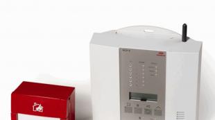
The detector is designed to work together with control panels (PCB) that receive a short circuit signal (SHPS) and have a loop of direct or alternating current.
The detector is not intended for use in chemically aggressive environments.
The detector design is ordinary in accordance with GOST 12997-84. Type of climatic modification - UHL category 3.1 according to GOST 15150-69 for operation in the temperature range from 0ºС to + 50ºС and relative humidity up to 95% at a temperature of + 35ºС.
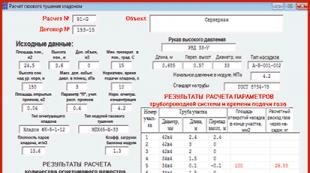
Key Specifications
- Nominal value of the detector operating temperature + 70ºС. The deviation of the detector temperature from the nominal value is not more than 5%.
- The inertia of the detector’s response (the time the medium temperature rises from + 25С to the moment the detector is triggered) at a temperature rise rate of 30 ° C / min is within 39 ... 162 sec. The inertia of the detector operation at a temperature rise rate of 3 ° C / min is within 433 ... 1120 sec.
- The detector is powered by ShPS directly from the control panel. Supply voltage range from 10 to 25 V.
- Current consumption in standby mode is not more than 50 μA.
- Protected surface of at least 25 sq.m.
- Indication of standby and alarm modes.
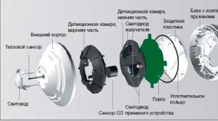
Structurally, the detector is made in a plastic case, consisting of a base and a decorative protective cover with a protruding trellised compartment. On the base there are two screw terminals for connecting the detector to the ShPS line and an electronic unit with a heat-sensitive element. At the edges of the decorative cover there are two mounting holes for mounting the detector on the protected object.
The circuit includes a diode bridge, a relaxation oscillator, a threshold electronic self-locking key, a temperature-sensitive element and an LED indicator.
The ambient temperature is measured by the detector discretely, for short measuring pulses, followed by a period of several seconds. Each measurement pulse causes a short flash of the LED. When the threshold temperature of the medium is reached, a large-amplitude pulse transfers the key to a stable closed state. The current of the key through the LED and the diode bridge shorts the ШПС, which causes a continuous glow of the LED and the operation of the control panel.
PASSPORT
Maximum thermal fire detectors FE 101-1A-A1, IP101-1A-A3 (hereinafter - the detectors) are designed to work as part of systems automatic installations fire extinguishing and fire alarms. According to the temperature and time of operation, the IP 101-1A-A1 and IP 101-1A-A3 detectors relate to classes A1 and A3 of NPB 85-2000, respectively. The detectors are designed for continuous round-the-clock operation in closed heated rooms together with reception and control devices having a fire alarm loop (ШПС) of direct or alternating current. The polarity of connecting the detector to the ShPS can be arbitrary. IP 101-1A-A1 detectors give a “Fire” signal to the alarm loop by increasing the current consumption when the ambient temperature exceeds a set threshold value.
The detector has an LED indication of the standby mode and the "Fire" mode. The detector has a microprocessor analysis of the temperature sensor signal, which allows to achieve high accuracy and low response inertia over the entire range of temperature rise rates.
The detector provides for the possibility of connecting Granit, Karat, UOTS-1-1A, and Quartz devices of the control and security fire-fighting devices (ППКОП) without the use of external limiting resistors. An external resistor connected to an additional terminal block connector can be used to incorporate other control panels in the ShPS.
IP 101-1A-A1 detector is not intended for use in chemically aggressive environments.
The detector version is ordinary in accordance with GOST 12997-84 for operation in the temperature range from minus 10 С to + 76 С and relative air humidity up to 93% at a temperature of + 40 С. The degree of protection of the detector is IP30 sheath according to GOST 14254-96.
Device and principle of operation
Structurally, the detectors are made in a plastic case, consisting of a base and a decorative protective cover with a protruding trellised compartment. On the base there are three screw terminals for connecting the detector to the ShPS line and installing, if necessary, an additional resistor. There are two mounting holes on the edges of the decorative cover for
mounting the detector on the protected object. In standby mode, the ambient temperature is measured by the detector discretely, for short time intervals, followed by a period of 6 ... 8 seconds. Each measurement is accompanied by a short flash of a red LED. When the threshold value of the medium temperature is reached, the detector switches to the “Fire” mode. In this mode, the residual voltage (between terminals 1 and 2) at a current of up to 20 mA does not exceed 8.5 V. The LED indicator in
broadcasters IP 101-1A-A1 and IP101-1A-A3 give double and triple flashes, respectively, with a frequency of 1 Hz.
Detectors maintain the “Fire” status after the end of exposure to elevated temperature. The detector enters the standby mode of operation when the ShPS voltage is turned off for at least 2 seconds.
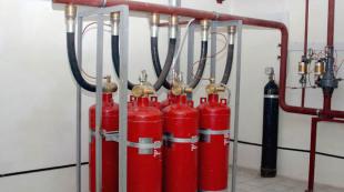
Any room - office, shop, apartment or warehouse, is constantly exposed to the risk of fire in it. It can be caused by anything - a shorted electrical wiring, a malfunction of electrical appliances, spontaneous combustion of a material, or a human factor. Any property owner wants to save his property from destruction. For organizations of a certain type of activity, the presence of a fire alarm is a prerequisite for opening an enterprise and carrying out work. A quite natural question arises: how to equip fire alarm at the facility inexpensively, reliably and in accordance with existing requirements. The answer to this question may be the installation of the IP 101-1A detector. This device combines reliability, simplicity and affordability.
Purpose and scope
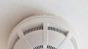
Fire detectors IP 101-1A-A3 and IP 101-1A-A1 are designed to detect signs of fire in heated warm rooms. An alarm occurs when the temperature rises above the threshold set by the sensor. Detectors have round-the-clock operation. A presentable appearance (a small cylinder made of white plastic) makes it possible to install them in rooms of the highest status.
Detectors work together with other monitoring sensors in the system fire alarm. Their design provides for the ability to connect to any DC cable.
IP 101 1A heat detectors can be mounted in such rooms:
- in warehouses and vaults for various purposes;
- in offices and government agencies;
- in the offices of management;
- at banks and post offices;
- in cafes, shops and stalls;
- in apartments and garages.
Devices respond only to heat, not responding to light sources, smoke or gas.
Device and principle of operation

The IP 101 1A detector is a compact device having a rather simple but functional device
It consists of the following parts:
- Body. The housing consists of a base and a cover with openings for air. The base is equipped with terminals for connecting the device to the alarm loop.
- The electronic unit. It has a light indicator, a heat-sensitive element, an electronic locking key and an electric diode circuit.
Space scanning is carried out automatically by periodically sending pulses to the thermocouple. When the control temperature is reached, the impulse that arises causes a short circuit in the circuit, the signal from which is fed to the control equipment. The LED is lit continuously, indicating the location of the triggered sensor.
Instrument Features
Heat detectors of the IP 101 series compares favorably with thermal sensors of other designs. They do not have fusible connections and bimetallic petals, which do not differ in high reliability and often give false signals.
In addition, these devices have the following features:
- the signal from the temperature sensor is analyzed by a microprocessor;
- the alarm is triggered by a change in electrical parameters;
- the presence of a light indicator that gives signals corresponding to the operating mode;
- active analysis of indoor air temperature;
- receiving power directly through the loop;
- lack of need of polar connection;
- adaptation to electrical parameters of fire alarm control panels.
The design of the lid allows you to aesthetically and harmoniously place the device in various rooms.
Advantages and disadvantages

Like any technical product, heat detectors have their pros and cons.
The advantages of the product include the following indicators:
- high speed of checking the temperature state (every 6 sec.);
- accuracy of exposure threshold by measuring current;
- lack of unreliable mechanical relays;
- no need to install a separate power line;
- lack of polarity of connection;
- no adjustment of the device resistance is required when connected to security systems;
- quick return to standby mode after operation;
- light weight and size, which allows you to place the device on thin substrates without embedded parts;
- affordable price (today - in the range of 150-225 rubles).
The disadvantages of the products in this series include:
- detectors cannot work in cold weather;
- chemically active medium is an obstacle to the installation of sensors;
- there is no possibility of using the detector in GSM systems.
Despite minor disadvantages, IP 101 detectors are well-deserved popularity and demand.
Key Specifications
The IP 101 1A detector has such specificationsto which potential buyers should pay attention:
- weight - 90-100 gr;
- size - 60-65 × 25-30 mm;
- supply voltage - 10-25 V;
- operating temperature - from 0 ° С to + 76 ° С;
- operation temperature - + 70 ° С (± 6 ° С);
- response time - 90-600 sec (depending on the rate of temperature increase);
- coverage area - 25 m;
- return to standby mode after shutdown - 2 sec;
- relative humidity in the rooms - up to 95%;
- average life is 10 years.
The manufacturer warrants the detector for 36 months after installation.
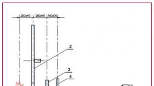
Installation of heat detectors
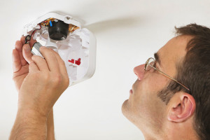
Devices can be installed simultaneously with other control sensors, as well as after their installation. The number of detectors installed depends on the technical capabilities of the security system.
Mounting devices is carried out to the ceiling, as in case of fire in this place is the highest temperature.
On a note: The sensor from the sensor is installed at a distance of not more than 5 m over the entire area of \u200b\u200bthe ceiling.
Detectors can be mounted on any material. It can be concrete, wood, drywall or plastic. For soft materials, wood screws are used, for hard ones - plastic dowels and screws.
After connecting the wires, the base of the case is fixed to the ceiling and the lid is closed. Connecting devices in a circuit is carried out in parallel.
Maintenance of devices is carried out quarterly and includes the following actions:
- External inspection for mechanical damage on the sensor housing and the loop line.
- Checking the reliability of mounting the sensor on the base.
- Cleaning the device from dust and dirt. Attention should be paid to cleaning the grilles through which air enters the sensor.
- Check the strength of the connection wires on the terminals.
- Checking the health of the device.
If a malfunction is detected, the device is sent to the manufacturer with the corresponding explanations, and a new detector is connected in its place.