Announcers ypres 3su manual fire
Description of IPR-3SU
IPR-3SU Manual fire detector, voltage 9-28V, 100uA, push-button start, 4 connection schemes, return to standby with a special key.
The IPR-3su manual announcer is used at facilities equipped with burglar and fire alarms and performs the function of a manual start in emergency situations.
Manual fire detector IPR – 3SU TsFSK.425232.001 TU (detector), used to manually start a fire alarm and security fire alarm. The detector is used for continuous operation with control panels (PPC) such as VERS, Granite, Rainbow, Signal and others. The detector provides reception and indication of the return signal (acknowledgment) when working with the control panel (for example, Versus or Granite). The detector is powered and the signal (fire) of the fire notification is generated via a two-wire fire alarm loop. The detector refers to products with periodic maintenance. The IPR-3SU detector transmits an alarm to the alarm loop when the detector button is pressed. After removing the force, the detector remains in the on state. The detector is transferred to its initial standby state by returning the button to its original position using the extractor (key) TsFSK.73431 1.008, which is included in the delivery.
Description
Manual fire detector, power supply 9 - 28 V, 100 μA, with button, 4 switching circuits
Appointment
The manual fire detector IPR-3SU is designed to manually turn on the alarm in fire and fire alarm systems.
Specifications
- Detector Type 2-wire (NC / NO)
- Explosion protection marking-
- Light indication″ Standby ″; "Fire"
- Supply voltage, B:
- - direct current-
- - alarm loopback9…28
- Consumption current, mA:
- - in standby mode no more0.1
- - in the "FIRE" mode25
- Maximum switching voltage, no more, V-
- Maximum switched current, no more, mA-
- Overall dimensions, mm90x105x50
- Degree of protection IP41
- Operating temperature range, ° С-40…+55
- Weight, no more than, kg0.11
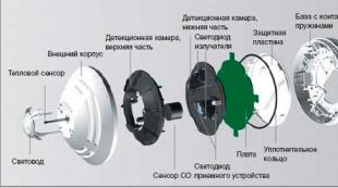
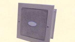
The IPR-3SU detector is a design consisting of a base, an inner cover and an outer cover. The detector has a built-in optical indication of standby mode (green light indicator) and operation (red light indicator).
The detector is used for round-the-clock continuous operation with reception and control devices (hereinafter referred to as the control panel) of the type PPK-2, PPS-3, Rainbow, Signal-20 and others. The detector receives and displays the return signal (acknowledgment) when working with the control panel (for example, the control panel-2 or PPS-3). The detector is electrically powered and the fire notification is transmitted via a two-wire alarm loop (hereinafter AL). The detector refers to products with periodic maintenance. The IPR-3SU detector sends an alarm signal to the AL when the drive element (button) of the detector is switched to the on state. After removing the force, the detector remains in the on state. The detector is put into standby mode by resetting the button to its original state using the TsFSK.734311.008 extractor included in the delivery package.
Connection Options:
. option 1 - simulation of a fire detector (PI) with a normally-closed contact (NZK), with acknowledgment;
. option 2 - imitation of active smoke PI;
. option 3 - simulation of PI with NZK for OPS devices;
. option 4 - simulation of PI with NZK with acknowledgment.
Option 1.
When the button is pressed, the detector includes an additional resistor in the loop, which is interpreted by the control panel as an alarm signal. After the control panel response signal (acknowledgment signal), the detector activates a red alarm indicator. After removing the force exerted on the button, the detector maintains the on state until the button is reset to its original position using the extractor.
Option 2
After pressing the button, the detector generates an alarm signal in the form of an abrupt decrease in internal resistance. In this mode, the detector does not have an internal current limiter, and the current value in the PPC loop when the detector is triggered is determined only by the characteristics of the PPC output current former or by installing an additional current-limiting resistance in each loop detector in the loop (+) circuit. At the same time, the alarming red indicator turns on.
Option 3
An alarming message for the control panel is a rupture of the AL line when the button is pressed. At the same time, the detector alarms (red indicator).
Option 4
After pressing the button, the AL line (-) is blocked by the diode, which serves as an alarm message for the control panel. The control panel reacts to the message by changing the polarity of the supply voltage, after which the detector's alarm lights up (red indicator).
They have firmly entered our lives, warning of a fire that has begun. But often people find fire before fire detectors. In this case, to manually start the alarm, special buttons are used - manual fire detectors.
Detector design
IPR-3SU announcer - fireman manual call point to bring the automatic fire alarm system with radial loops to the active state. The sensor is designed for connection to a control panel with two-wire radial loops. When changing its state, the device changes the resistance of the signal loop. The detector is powered from the control panel via a signal loop. To bring the device into an alarm state, it is necessary to put the drive element in the on position. After that, the button is fixed in the alarm state. To return the detector to armed mode, press the button again. The device button is protected by a transparent cover that protects it from accidental pressing.
Structurally, the detector consists of a base and two covers - internal and external. To indicate the status, it is equipped with a red and green LED indicators, indicating a blinking standby or alarm modes of operation. Sensor body color is red.
Technical specifications
A universal solution for analog APS is the manual fire detector IPR-3SU. Sensor specifications are listed below:
- Contacts normally closed or open.
- Optical indication of work / alarm.
- Supply voltage 9-28 V.
- Standby current 0.1 mA.
- Alarm current 25 mA.
- The force of inclusion 12-18 N.
- Maximum dimensions - 90x105x50 mm.
- Weight - 110 g.
- Execution of the case IP41.
- Operating temperature - -40 .. + 50 degrees.
- Relative humidity 93%.
- The average life of 10 years.
- MTBF of 60,000 hours.

Detector Installation
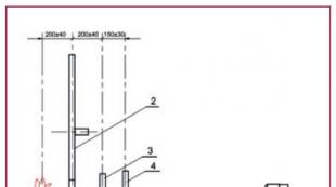
Instrument Installation fire protection regulated by SP5.13130.2009. In accordance with this set of rules, the IPR-3SU manual fire detector must be installed at a height of 1.5 m from the floor level. Installation locations - exits from rooms, from floors, escape routes - at least every 50 meters. The sensor must be installed on the base of non-combustible material, at a distance of not less than a meter from heating appliances and electrical equipment. Fastening the base of the device to the bearing surface is carried out with screws, a diagram of the template for marking the surface is given in the passport for the manual fire detector IPR-3SU.

Device connection
The IPR-3SU manual fire detector will be connected to two-wire radial loops as normally closed or normally open sensors. To select one of the connection options in the sensor, jumpers are provided:
- Simulation with normally closed contacts and the ability to acknowledge.
- Fire Smoke Detector Mode.
- Simulation of a fire sensor with an NC contact for a fire alarm.
- Loopback for alarm systems.
On the sensor board, there are two pads with screw terminals for connecting the signal cable wires and an additional current-limiting resistor. The resistance of the resistor is determined depending on the switching circuit and the control panel. The IPR-3SU manual fire detector should be connected to a signal cable that maintains its operability in a fire. For laying such loops, a fire-resistant cable line based on a cable in the execution of FR and metal cable-bearing elements is used.
IPR-3SU is designed to manually turn on the alarm in fire and fire alarm systems.
Technical characteristics of IPR-3SU:
- Supply voltage from the alarm loop, V 9.0 ... 28.0
- Current consumption in standby mode, no more, mA 0.1
- Operating temperature range, ° С -40 ... +60
- Overall dimensions, mm 90x90x45
- Weight, no more, kg 0,35
The IPR-3SU detector is a design consisting of a base, an inner cover and an outer cover. The detector has a built-in optical indication of standby mode (green light indicator) and operation (red light indicator).
The detector is used for round-the-clock continuous operation with reception and control devices (hereinafter referred to as the control panel) of the type PPK-2, PPS-3, Rainbow, Signal-20 and others. The detector receives and displays the return signal (acknowledgment) when working with the control panel (for example, the control panel-2 or PPS-3). The detector is electrically powered and the fire notification is transmitted via a two-wire alarm loop (hereinafter AL). The detector refers to products with periodic maintenance. The IPR-3SU detector sends an alarm signal to the AL when the drive element (button) of the detector is switched to the on state. After removing the force, the detector remains in the on state. The detector is put into standby mode by resetting the button to its original state using the TsFSK.734311.008 extractor included in the delivery package.
Connection Options:
- option 1 - simulation of a fire detector (PI) with a normally-closed contact (NZK), with acknowledgment;
- option 2 - imitation of active smoke PI;
- option 3 - simulation of PI with NZK for OPS devices;
- option 4 - simulation of PI with NZK with acknowledgment.
Option 1. When the button is pressed, the detector includes an additional resistor in the loop, which is interpreted by the control panel as an alarm signal. After the control panel response signal (acknowledgment signal), the detector activates a red alarm indicator. After removing the force exerted on the button, the detector maintains the on state until the button is reset to its original position using the extractor.
Option 2 After pressing the button, the detector generates an alarm signal in the form of an abrupt decrease in internal resistance. In this mode, the detector does not have an internal current limiter, and the current value in the PPC loop when the detector is triggered is determined only by the characteristics of the PPC output current former or by installing an additional current-limiting resistance in each loop detector in the loop (+) circuit. At the same time, the alarming red indicator turns on.
Option 3 An alarming message for the control panel is a rupture of the AL line when the button is pressed. At the same time, the detector alarms (red indicator).
Option 4 After pressing the button, the AL line (-) is blocked by the diode, which serves as an alarm message for the control panel. The control panel reacts to the message by changing the polarity of the supply voltage, after which the detector's alarm lights up (red indicator).
Features: Designed to work with control panels with alternating voltage in the cables
product Code: 701304