A clear explanation of how thief beacons work. VOR radio beacon combined with a range finder. Radio system vor
The tasks solved by on-board equipment in the “Navigation” mode (hereinafter “VOR”) are set out in § 3.1. The main task is to measure the azimuth (magnetic bearing) to the radio beacon (AM), i.e. the angle in the horizontal plane between the direction of the magnetic meridian passing through the center of gravity of the aircraft and the direction to the radio beacon.
The omnidirectional radio beacon VOR of the international system is part of the azimuth-ranging short-range radio navigation system, which is adopted by ICAO member countries as a standard system. Its azimuthal part is made up of VOR radio beacons, and the rangefinder part is made up of DME (distance measuring equipment, which means range measuring equipment).
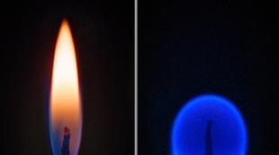
VOR radio beacon designed to set information about the azimuth of an aircraft, operates in the range of 108...117.95 MHz and is available in two versions: category A with a range of up to 370 km and category B up to 46 km. At the carrier frequency, it emits reference and variable phase signals at 30 Hz. The phase reference signal is emitted by the antenna, which forms a circular radiation pattern 2 (Fig. 3.14), and its phase (30 Hz) in all directions relative to the beacon is constant. The carrier frequency of the reference phase signal is amplitude modulated by a voltage subcarrier with a frequency of 9960 Hz, which in turn is frequency modulated by a voltage with a frequency of 30 Hz with a frequency deviation Δf= ±480 Hz.
The variable phase signal is emitted by the antenna, which forms the radiation pattern 1 in the form of a figure eight and rotates at a frequency of 30 rps (30 Hz). It is amplitude modulated with a voltage of 30 Hz. During one rotation of the antenna, the phase of the variable phase signal changes from 0 to 360°. The radio beacon is adjusted so that in the direction of the magnetic meridian passing through the location where the radio beacon is installed, the signals from the reference U of and variable U p f phases coincided, but in other azimuthal positions they would differ in phase. The antenna radiation patterns of both signals in space are added up, forming the resulting 3 with maximum radiation in the direction 1 to the magnetic meridian. The coincidence of the phases of the signals in the direction of the magnetic meridian is the starting point. In this direction the phase shift Dφ equal to zero, in other directions (II-IV)
Rice. 3.14. Radiation pattern of VOR beacon antennas
varies from 0 to 360. Thus, information about the aircraft azimuth is contained in the phase shift between the reference and variable phase signals; the AM azimuth is determined by the relation AM = AC ±180°.
To identify VOR beacons, the carrier frequency is manipulated by Morse code with a 1020 Hz signal. Call signs can also be transmitted by voice using magnetic recording. In addition, a message can be transmitted to the aircraft at the carrier frequency.
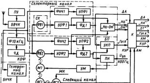
Structural scheme onboard equipment is shown in Fig. 3.15. High-frequency VOR beacon signals enter the device through the antenna UNP per block BVChK, which, using the control panel, is tuned to the frequency of the VOR beacon. In the block BVChK The reference and variable phase signals are amplified, converted and detected. A variable phase signal is isolated at the load of the amplitude detector U pf frequency 30 Hz, phase reference signal U of, representing a frequency-modulated oscillation with a frequency of 9960 Hz, frequency-modulated by a voltage with a frequency of 30 Hz, and identification signals with a frequency of 1020 Hz. They come to the block BNCHK. In the block BNChK via 10 kHz filter and frequency detector (BH) signal is highlighted U of frequency 30 Hz, which enters the tracking (automatic) and through the course selector (SC) into the selector (manual) channels. These channels also receive a signal U pf frequency 30 Hz. In addition, the signals U of And U pf used in the "On-From" display device.

Rice. 3.15. Block diagram of on-board equipment in "VOR" mode
Tracking channel measures beacon azimuth by measuring the phase shift between signals U of And U pf frequency 30 Hz.
The main element of the channel is a phase detector (phase-sensitive rectifier) FD2. To it through a reference phase signal amplifier UOF2 a signal arrives U of, and it comes through a phase shifter FV2, which is driven by a motor M1. The phase of the phase shifter's output voltage is proportional to the angle of rotation of its rotor. In addition, the detector FD2 a signal arrives U pf, which is highlighted by the filter LPF2 and is amplified by a variable phase signal amplifier UPF2.
Detector FD2 generates voltage ± U y, the value of which depends on the phase shift between the signals U of And U pf, i.e., from the azimuth AM. This voltage is converted by a voltage converter Mon into an alternating frequency of 400 Hz of the corresponding phase and amplitude, which is amplified by a power amplifier and supplied to the engine M1. If the sun is in the direction of the magnetic meridian, the phase shift between the signals U of And U pf equal to zero, equal to zero voltage U y on detector load FD2, and the engine does not work. At a different azimuthal position of the aircraft, the detector generates a voltage ± U y. which is converted into a voltage with a frequency of 400 Hz, and after amplification it is supplied to the engine M1. When it rotates, the angular position of the phase shifter rotor changes, which leads to a change in the phase of the signal U of. This happens until its phase matches the phase of the signal U pf and voltage ±U y will not be equal to zero. Thus, the engine rotation angle M1 and the phase shifter rotor is proportional to the phase shift between the reference and variable phase signals, i.e., azimuth.
Azimuth information from the sensor BC1 type BSKT enters through the device TO to indicators PNP. At the same time, the CUR angle is determined in the tracking channel (Fig. 3.16, a) by algebraically adding (subtracting) the AM azimuth and the MK heading (CUR = AM - MK). A differential sensor is used for this BC2 type BSKT, the rotor of which is rotated by the engine at an angle proportional to the azimuth AM. The stator winding is connected to the sensor of the heading system or device that measures MK (BGMK-2 - gyromagnetic compass unit of the Tu-154M aircraft and BSFC-1 - basic heading system of the Yak-42 aircraft). In the rotor winding of the sensor BC2 a voltage proportional to the CUR is generated, information about which is transmitted to the RMI (radiomagnetic indicator) and PNP-72.

Rice. 3.16. Determination of the control angle (a) and flight of the aircraft at a given azimuth (b)
Selector channel(see Fig. 3.15) determines the angular (lateral) deviation ΔA of the aircraft from the line of a given path (passing through the beacon (Fig. 3.16, b), which is set manually by the specified azimuth A back. The principle of operation is based on a comparison of azimuth A of the back track line and the current azimuth to the AM T beacon. This comparison takes place in the detector FD1, to which the signal is received U pf containing information about the current AM T azimuth, and a signal U of, coming through the phase shifter FV1. It is structurally located in the course selector SK u is controlled by the "Course" knob (see Fig. 3.5) and contains information about the specified azimuth A is the back of the track line. When an aircraft is flying along the line PAP azimuths AM T and the butts are the same and the voltage ±U y detector FD1, proportional to the deviation YES is equal to zero. When the aircraft deviates, the azimuth changes AM T and voltage ± U y. Deviation signal DA via device TO goes to PNP devices and automatic control systems (SAU-42, ABSU-154).
Continuous parameter monitoring device(UKP) generates the readiness signal "Got.K" in the form of a voltage of +27 V. Voltages are supplied to it U y with detector FD1 And FD2 selector and tracking channels, where they are compared, and during normal operation of the on-board equipment, the “Get.K” signal is issued. It's through a switching device TO goes to the "K" blenders of the PNP devices, the "Kl", "K2" lamps of the mode selector and the AFS "Lily" system of the Yak-42 aircraft.
Display device - "On-From" provides visual signaling of flights to and from the lighthouse. It is controlled by signals U of frequency 30 Hz selector (A back) and tracking (AM T ) channels, which are removed after the phase shifters of these channels. When flying to the lighthouse, these signals are in phase and the device produces an signaling voltage “On” in the form of a voltage of +27 V. When flying over the lighthouse, the azimuth AM changes by 180°, therefore the phase of the signal changes U of tracking channel 180° and at the input of the device "To-From" signals U of both channels will be out of phase, it produces a voltage for the "From" signaling. The indicators used are the “Na” and “From” lights (Tu-154M aircraft) and flight direction indicators with the symbols “A” (Na) and “V” (From) of PNP devices in the form of a bipolar magnetoelectric indicator index.
In the block BNChK separate cascades and phase detectors are used in the “VOR” and “Landing” modes when monitoring the landing course line in the SP-50M, SP-68 systems (see § 3.2). The phase detector of the tracking (automatic) channel in the "Landing" mode is used in the control channel, and the selector (manual) channel - in the main channel. Switching of detectors is carried out by special circuits - switches. The telephone channel of the "VOR" mode is common with the heading channel of the "Landing" mode.
To use on-board equipment in the “VOR” mode, the VOR beacon frequency is set on the control panel and the required azimuth of the given path line is entered using the course selector.
Omnidirectional beacon(English) V ery high frequency O mni directional radio R ange abbr. VOR). Provides information about the azimuth of the aircraft. The radio beacon can operate either independently or in conjunction with a DME rangefinder, forming an azimuth-rangefinder short-range navigation system VOR/DME.
The VOR beacon emits on one of 160 carrier frequencies (ranging from 108 to 117.975 MHz in 50 KHz steps) reference and variable phase signals frequency 30Hz.
An amplitude-frequency modulated reference phase signal containing a frequency-modulated subcarrier(9960Hz with deviation plus or minus 480Hz) is emitted by a fixed omnidirectional antenna. An amplitude-modulated variable-phase signal with a frequency of 30 Hz is emitted by a rotating (30 rps) directional antenna with a figure-of-eight radiation pattern.
The directional patterns folding in space form a field of variable amplitude, changing with a frequency of 30 Hz. The VOR beacon is oriented so that the phases of the reference and alternating signals coincide in the direction magnetic north meridian. At the moment when maximum directional pattern of the rotating field directed there, signal frequency subcarrier has a maximum value (1020Hz). In other directions, the phase shift varies from zero to 360 degrees. In a simplified way, you can think of a VOR as a radio beacon that emits its own individual signal in each direction. The number of such “azimuth signals” is determined only by the sensitivity of the on-board equipment to the magnitude of the phase shift, directly proportional to the current azimuth of the aircraft relative to the radio beacon. In this context, instead of the concept "azimuth" the term is used radial (VOR Radials). It is generally accepted that the number of radials is 360. The radial number coincides with the numerical value of the magnetic azimuth.
The on-board VOR indicator, in addition to indicating the azimuth, allows you to navigate the aircraft in the “from” and “to” modes of the radio beacon at a given azimuth. For this purpose, the VOR indicator has corresponding bars showing the deviation of the aircraft from the LZP. Accordingly, the LZP must pass directly through the beacon itself.
To identify VOR beacons, the carrier frequency is manipulated using Morse code with a 1020 Hz signal. In addition, call signs can be transmitted by voice using magnetic recording.
A similar principle of constructing a goniometric system allows, due to the complexity of the ground part of the complex, to simultaneously simplify (read - reduce the dimensions and weight) of the equipment installed on board the aircraft. Undoubtedly, this was one of the main factors that determined the widespread use of VOR systems, including in small aviation.
VOR beacons are available in two versions:
- category A(with a range of about 370 km at a flight altitude of 8-10 km to ensure flights along air routes);
- category B(with a range of about 40 km to service the airfield area).
Among domestic equipment, an analogue of the VOR/DME system can be called RSBN, the functional purpose of which is generally the same - determining range and azimuth. However, to solve additional navigation problems (mostly military ones), the RSBN is built on different principles and requires the installation of completely different equipment on board.

Limits on height and range of signal reception.
The VOR navigation goniometric channel is designed to determine the azimuth of the aircraft relative to the radio navigation point at which the system’s ground equipment is installed. The goniometric channel includes ground and airborne equipment. The ground equipment is a radio beacon that emits signals, the reception and processing of which on board the aircraft makes it possible to determine its azimuth. The onboard equipment is a receiver indicator, the principle of operation of which is determined by the azimuth measurement method used in the channel. With this construction of the azimuthal channel, its capacity is not limited. Currently, there are three main modifications of MV range goniometric systems:
with measurement of the phase of the AM oscillation envelope (VOR);
with two-stage phase measurement (PVOR);
using the Doppler effect (DVOR).
VOR
. VOR beacons have two transmitting antennas:
omnidirectional antenna A 1 with a directional pattern (DNA) in the horizontal plane;
directional antenna A 2 with a radiation pattern in the horizontal plane.
In any azimuth direction the value of the radiation pattern A 2 characterized by size.
Antenna A 1
![]() (1.1)
(1.1)
with amplitude .
Antenna A 2 in any azimuthal direction creates a field
with amplitude ![]() . (1.3)
. (1.3)
Typically, for VOR beacons the condition is met.
The radiation patterns of the VOR beacon antennas are shown in Fig. 1.6(a).
High-frequency signals are generated by a single transmitter and emitted by antennas that have a common phase center. When fields are added in space, the total field of an omnidirectional PM is formed (Fig. 1.6(b)) ![]() .
. 
Rice. 1.6. VOR antenna radiation patterns
Taking into account expressions (1.2) and (1.3), the value of the total field can be expressed
 . (1.4)
Directional pattern A 2 rotates in a horizontal plane with angular velocity
Where n– frequency of rotation of the bottom per minute.
Duration of one revolution T equal to the rotation period, , and frequency . The VOR speed is n=1800 rpm (F=30 Hz).
Beam position A 2(the position of its maxima) is a function of time. Rotation of the antenna will cause a periodic change in the total field. Let us denote the ratio of the amplitudes and, substituting the values and into (1.4), we obtain
The result is a field with amplitude modulation depth, modulation frequency, and azimuth-dependent envelope phase. The oscillations received by the on-board receiver can be represented by the expression
Where TO– coefficient taking into account attenuation.
After amplification and detection, low frequency voltage can be isolated
, (1.7)
the phase of which contains information about the aircraft's azimuth:
. (1.8)
To isolate this information on board the aircraft, it is necessary to have a reference vibration that carries information about the instantaneous position of the bottom. This information must be embedded in the reference oscillation phase ![]()
with the current phase value
(1.9)
corresponding to the angular position of the bottom at a given time t.
If such a reference voltage is available on board the aircraft, the aircraft azimuth can be determined as the phase difference between the reference and azimuthal signals (1.8) and (1.9):
For the onboard meter to operate, a reference signal is required, which is the same for all aircraft. This signal must be transmitted over a separate communication channel. In order to reduce frequency communication channels, the reference signal in these systems is transmitted at the same carrier frequency as the azimuthal one. The separation of the azimuthal and reference signals into channels occurs on the receiving side using the method of frequency selection of the combined signal detected by amplitude. This opportunity arises when using double amplitude-frequency modulation to transmit the reference signal.
Let's consider the formation of signals by ground equipment and the operation of on-board equipment using the example of a simplified block diagram of the VOR channel (Fig. 1.7).
High-frequency frequency oscillations are formed in the transmitter (PRD). In a power divider (PD), the RF signal is divided into two channels. Part of the power goes to the rotating antenna A 2. The antenna rotation frequency is determined by the control unit (CU) and is equal to F=30 Hz. Radio beacons used various methods of antenna rotation. In the first radio beacons, the antenna was rotated mechanically using an electric motor. Another method involves the use of goniometric antenna systems. Later, methods were developed for electronic rotation of the bottom (electronic goniometer method), in which the effect of rotating the bottom is achieved by feeding two mutually perpendicular directional antennas with figure-of-eight patterns. The antennas are powered by balanced-modulated oscillations with a phase shift of the modulation envelope by 90°. Antenna A 2 an electromagnetic field is created (1.2).

Rice. 1.7. VOR channel block diagram
Antenna A 1 is non-directional and is designed to form a total radiation pattern of the “cardioid” type and transmit a reference signal. To generate a signal with double amplitude-frequency modulation, oscillations are selected whose frequency is much higher than the rotation frequency of the bottom, but significantly less than the frequency of the carrier oscillations, and these oscillations are used as auxiliary ones. Auxiliary vibrations are called subcarrier, for which the condition must be met ![]() , where is the frequency of subcarrier oscillations. For a VOR system, the subcarrier frequency is F P =9960 Hz.
, where is the frequency of subcarrier oscillations. For a VOR system, the subcarrier frequency is F P =9960 Hz.
In the subcarrier modulator (MS), frequency modulation of the subcarrier is carried out using reference oscillations at the frequency F OP =30 Hz with frequency deviation ΔF P =480 Hz at modulation index . In an MHF modulator, high-frequency oscillations are amplitude modulated by the subcarrier voltage with a modulation depth.
Antenna A 1 creates a field with tension
where is the amplitude modulation coefficient; – frequency modulation coefficient; – subcarrier frequency deviation.
Total field
![]()
affects the antenna of on-board equipment A 0. At the antenna output, a total oscillation of the form is obtained
The amplitude-frequency spectrum of the total oscillation is shown in Fig. 1.8(a).

Rice. 1.8. Amplitude-frequency spectrum:
a) received signal;
b) envelope of the received signal
The onboard equipment must separate the azimuthal and reference signals from the total and compare them in phase.
After converting the total signal in the receiving device (RD), amplifying it and detecting it with an amplitude detector, an envelope containing azimuthal and reference signals of the form
, (1.12)
where and are the amplitudes of the components of the total signal.
From the spectrum of the signal (1.12), presented in Fig. 1.8(b), it can be seen that the azimuthal and reference signals can be isolated by frequency selection. For this purpose, the signal from the PRM output is fed to two filters F1 and F2.
In filter F1, tuned to frequency ( f=30 Hz), an azimuthal signal or a variable phase signal is isolated, and in the F2 filter, tuned to the subcarrier frequency ( f=9960 Hz), a frequency-modulated subcarrier wave is highlighted. After symmetrical limitation in the limiting amplifier (CA), a reference oscillation is isolated in the frequency detector (FD).
As a result of the transformations we obtained:
azimuth signal;
reference signal
The reference voltage is supplied to phase shifters FV1 and FV2. In the initial position, the FV1 axis is rotated at an arbitrary angle b, which causes an additional phase shift of the reference voltage by the amount b
AND ![]() . (1.13)
. (1.13)
The azimuthal and reference voltages are supplied to the phase detector FD1. Phase difference between input voltages
Voltage at the output of the phase detector FD1:
This DC voltage is converted (in PNV) into an error signal with a frequency of 400 Hz and supplied to the control winding of the electric motor (DM), which rotates the rotor axis of the phase shifter FV1 until the phase difference becomes zero. At the same time. Thus, the rotation angle of the FV1 phase shifter rotor becomes equal to the aircraft azimuth. The FV1 axis is connected to the axis of the selsyn sensor (SD), which transmits measurement results to azimuth indicators.
The VOR system allows the aircraft to fly at a given azimuth. For this purpose, FD2 and FV2 were introduced into the circuit. The FV2 axis is rotated manually and set to a given angle. In this case, the phase of the reference voltage additionally shifts by an amount and becomes
![]() .
(1.16)
.
(1.16)
This voltage is supplied to the input of FD2. The second input is supplied with azimuthal voltage with phase
![]() .
.
Phase difference between azimuthal and reference voltages at the FD2 input
After phase detection according to (1.15) at the detector output
.
When , and the azimuth of the aircraft coincides with the given direction. This problem is solved when the aircraft flies to or from the VOR beacon. To indicate a flight to or from a radio beacon, FD3 is introduced into the circuit and fed to it.
Radio beacons, just like regular beacons, are used for navigation and to determine the location of ships. To determine the direction to the radio beacon, the pilot needs a radio compass.
NDB and VOR
N.D.B. (Non-Directional Beacon) – drive radio station (PRS) – a radio beacon operating on medium waves in the range of 150-1750 kHz. The simplest AM-FM home radio receiver is capable of receiving signals from such beacons.
Residents of St. Petersburg can tune the receiver to a frequency of 525 kHz and hear Morse code: “PL” or dot-dash-dash-dot, dot-dash-dot-dot. This is the local NDB radio beacon that welcomes us from Pulkovo.
One of the Virpil colleagues, comparing the operating principles of NDB and VOR beacons, gave an interesting analogy. Imagine that you and a friend are lost in the forest. Your friend shouts, “I’m here!” You determine the direction of the voice: judging by the compass, the azimuth is, say, 180 degrees. This is NDB.
But if your friend shouted: “I’m here - the radial is 0 degrees!” Now this is VOR.
VOR (VHF omnidirectional radio range) – Omnidirectional azimuthal radio beacon (RMA), operating at frequencies in the range 108 – 117.95 MHz.
NDB sends the same signal in all directions, and VOR broadcasts information about the angle between the direction to the North and the direction to the aircraft relative to ITSELF or in other words - RADIAL.

Unclear? Let's put it another way. The VOR in each direction away from itself - from 0 to 360 degrees - emits a unique signal. Roughly speaking, 360 signals in a circle. Each signal carries information about the azimuth of any point relative to the beacon where this signal is received. These beam signals are called radials. To the North it sends a signal of 0 (zero) degrees, to the South – 180 degrees.
If your amateur AM/FM receiver could receive VOR frequencies and decode them, then upon receiving such a signal, you would hear: “I am an SPB beacon, 90 degree radial.” This means that your body is located strictly in the East FROM the lighthouse - 90 degrees. This means that if you go strictly to the West - heading 270 degrees - then sooner or later you will see this lighthouse in front of you.
The most important property of VOR for us is the ability to automatically pilot to the signal source of this beacon with a selected course. To do this, the navigation receiver is tuned to the radio beacon frequency, and the approach course to it is selected on the autopilot panel.

How to determine the distance to the lighthouse? How long does it take to get there? That's what DME is for.
DME (Distance Measuring Equipment) – Omnidirectional ranging radio beacon or RMD. His task is to give us information about the distance between him and our plane.
DME is usually combined with VOR, and it is very convenient to have information about our position relative to the beacon and the distance to it. Only, in order to determine this distance, the aircraft must send a request signal. DME responds to it, and the on-board equipment calculates how much time has passed between sending the request and receiving its response. Everything happens automatically.
VOR/DME is a terribly useful thing when landing.
ILS
Course and glide path system - ILS. This is a radio navigation approach system. Perhaps 90 percent of the airfields where large planes like ours land are equipped with it.
The ILS should be known as the “Our Father.” ILS makes landing not only comfortable, but also safe. There are airfields where other landing methods are impossible or even unacceptable.
From the name of the system it follows that according to it the aircraft is automatically aligned with the axis of the runway (heading system) and automatically enters the glide path and maintains it (glide path system).
There are two radio beacons installed on the ground: a localizer and a glide slope.


Course beacon– KRM – ( LOCALIZER) points the aircraft towards the runway in a horizontal plane, that is, along the course.
Glide path lighthouse– Timing belt – ( GLIDESLOPE or Glidepath) guides the aircraft onto the runway in a vertical plane - along the glide path.
Radio markers
Marker beacons are devices that allow the pilot to determine the distance to the runway. These beacons send a signal upward in a narrow beam, and when the plane flies directly over it, the pilot knows about it.
general description
The VOR-900 Omnidirectional/Marker Beacon Receiver (VOR/MKR) is a solid-state, microprocessor-controlled omnidirectional radio (VOR) receiver and marker beacon receiver (MKR). It combines the functions of a 160-channel VOR receiver in the range of 108-117.9 MHz with a frequency step of 50 kHz and a single-channel 75 MHz marker beacon receiver. Tuning of the VOR/MKR receiver is carried out either through the FMS aircraft navigation systems (main tuning tool) or two radio control panels RMP (backup tuning tool).
The VOR-900 receiver has two separate functions. The first of these is to receive, decode and process bearing information from the received omnidirectional beacon signal. The second is to receive, decode and process the received beacon signals.
The omnidirectional beacon function provides digitized bearing, visual and acoustic ground station identification information.
The radio marker function provides visual and audible identification when located above the radio marker transmitter by indicating in the cockpit three cases: far, middle, near, accompanied by signals of one of three audible tones: 400 Hz, 1300 Hz, 3000 Hz.
System components
The VOR/MKR system includes the following equipment and associated hardware:
- two receivers;
- one (double) omnidirectional beacon antenna;
- one (double) marker antenna;
- one marker beacon divider.
Principle of operation
VOR/MKR receivers are configured through FMS blocks or RMP panels via the ARINC 429 bus. The VOR receiver is configured for 160 channels in the range of 108-117.95 MHz; in the range of 108-112 MHz, channels with a frequency of an even number of tenths of a megahertz are used. The marker receiver operates at a frequency of 75 MHz.
Information from marker beacons is typically used for high precision approaches, but can also be used on route segments when received from "waymarkers".
VOR information can be used during all phases of flight where ground VOR beacons are located and properly operational.
Because the VOR-900 receiver is responsible for performing two separate aircraft navigation functions, two independent antennas are used to provide input signals to the separate receiver systems. The VOR receiver receives the incoming signal from the VOR antenna. This receiver detects, filters and amplifies bearing and audio information before further processing. The TO/FROM indication is also derived from the received signal. The electronic display system (CDS) displays VIUD course deviation (5 degrees per dot) as a function of the heading bar setting.
The marker receiver receives a signal with a frequency of 75 MHz. when the aircraft flies over the location of the marker transmitter. The detected signal is filtered and amplified before being transmitted to the detector. The audio signal output from the 75 MHz carrier frequency is fed to a system of three filters, each configured to pass a single frequency.
The filter frequencies are: 400 Hz, 1300 Hz and 3000 Hz, modulated in Morse code. These audio tones correspond to the far, middle and near markers on the approach path.
The sound signal from the filter is sent through an audio frequency amplifier to the aircraft audio distribution systems. The signal is also included in the VOR receiver output word, which is sent over the ARINC 429 bus for display on the CDS.
The symbology display “O”, “M”, “I” represents, respectively, the passage of the outer, middle and near markers during an instrument approach. In case of overflow of track beacons and fan beacons, the received and demodulated audio signal with a frequency of 3000 Hz includes the symbol “I”.
The VOR antenna is equipped with two C-type coaxial antenna ports. Both VOR/MKR receivers are thus connected directly to the antenna and do not require a signal distributor. The VOR antenna is located in the fin under the radome.
The marker antenna is designed with a coaxial antenna port. To generate a signal, a signal divider from the marker antenna is also installed on two VOR/MKR receivers.
System management
Configuration of VOR/MKR receivers is carried out through the FMS blocks (main configuration) or RMP panels (backup configuration).
The selection is based on the ARINC 429 standard identity checksum (SDI). Each FMS sends the tuning data to receiver VOR1 with SDI = 01, and to receiver VOR2 with SDI = 10. Each receiver receives tuning data with the correct SDI value.
VOR data is displayed on the flight deck displays when VOR aids are selected as the navigation source.
Information from markers (I, M, O) is automatically received and processed when the aircraft flies over radio markers or waymarks. These devices transmit on a fixed frequency of 75 MHz, so no cockpit configuration is required.
Receiver VOR-900
The VOR-900 Omnidirectional/Marker Beacon Receiver (VOR/MKR) is a solid-state, microprocessor-controlled omnidirectional radio (VOR) receiver and marker beacon receiver (MKR). It combines the functions of a 160-channel VOR receiver in the range of 108-117.9 MHz with a frequency step of 50 kHz and a single-channel 75 MHz marker beacon receiver.
Functional structure
The VOR-900 receiver provides the transmission of bearing and marker information to the aircraft navigation system and the electronic display system in the cockpit. Bearing information is extracted from amplitude modulated signals in the range 108-117.5 MHz. The electrical units that demodulate signals and process bearing information are processor A2, power supply A3, VOR receiver A4 and marker receiver A5.
Rear Interconnect A1
The rear interconnect A1 provides all the interconnect wiring and connectors required between it and the A2 processor. It also contains high intensity electromagnetic field (HIRF) filters and provides a ground that is isolated from the radio ground.
Processor A2
The microprocessor-based A2 processor digitizes the output signals of the A4 VOR receiver to recover the phase information of the VOR signal. The A2 processor consists of a signal processor, a system processor, random access and read-only memories, analog-to-digital converters, a main reset circuit, and buffers.
Power supply A3
The power supply accepts primary power at 115V 400Hz AC. At the output of the power supply, secondary voltages are formed at the level of +12V, -12V, +5V, -5V.
VOR A4 receiver
VOR receiver Ф4 receives and demodulates the modulated VOR beacon signal. The A4 receiver consists of an RF/IF stage, an envelope detector, and an automatic gain control stage.
Marker receiver A5
The A5 marker receiver includes a mains filter, cascades for generating output and intermediate frequency radio signals, an amplitude modulation detector and an amplifier with an automatic gain control system. The marker receiver amplifies the signal, selects the audio component, and outputs the result to the automatic gain control circuit.
A6 motherboard
The A6 motherboard provides intercomponent wiring and installation of electrical components A2, A3, A4, A5.
A7 Maintenance Processor
Maintenance processor A7 monitors and stores fault messages from processor A2. The service processor consists of a microprocessor, read-only and random-access memory, a main reset circuit, and buffers.
Mechanical design
The receiver is made according to the ARINC 600 standard in a package with dimensions of 3 MCUs. The connector is also made according to ARINC 600. A special test connector is located at the rear of the unit, which makes testing easier.
The receiver consists of an aluminum housing that provides mounting for the main components: rear interconnect A1, processor A2, power supply A3, VOR receiver A4, marker receiver A5, motherboard A6 and maintenance processor A7.
The body design minimizes the number and length of seams. The design is sealed and shielded from interference. Low resistance values are provided by wide overlaps and minimal gaps. A spring metal gasket around the perimeter provides dense isolation from the influence of RF interference when closed.
Each module inside the VOR-900 receiver is secured to the frame with screws to ensure good electrical grounding, minimize electrical noise, and hold the module securely to prevent vibration. Each module has a metal casing for better protection against external radio interference. The side covers are secured with captive screws. Once the screws have been loosened, the side covers can be hinged at the rear of the unit. The maintenance processor is mounted on the outside of the left housing. A ribbon cable connects it to the instrument's processor. The A2 processor and A3 power supply are mounted on the left side of the right metal panel, which forms the center of the frame. The motherboard is mounted between the device processor and power supply, and the central panel of the chassis. The motherboard provides electrical connections between components on opposite sides of the chassis. The marker receiver and VOR receiver are mounted on the right side of the center panel of the chassis. Ribbon cables are used to connect components mounted on the center panel of the frame to the A1 interconnect mounted at the rear of the frame.
Interconnect A1 is located in the rear section of the chassis. The cover at the rear of the chassis can be removed without the need to remove the side covers. The ARINC 600 connector is mounted directly on the interconnect board. The connector pins are inserted from the front and pass through the connector directly into the male connector board. A braided metal spacer surrounds the rear connector to protect against radiated electromagnetic interference.
A small board containing LED indicators and a test switch is mounted inside the front panel of the VOR-900 receiver.
Specifications
General characteristics:
- VOR receiver frequency range: 108.00 - 117.95 MHz with frequency increments of 50 kHz;
- marker receiver frequency: 75 MHz, fixed setting;
- complies with the requirements of ICAO Annex 10 for immunity to frequency modulation radio emissions;
- meets the requirements for exposure to high intensity fields (HIRF) at a “substantial” level.
- meets DO-178A/DO-160C$ requirements
- increased resistance to power interruptions;
- Improved integrated control hardware interface.
Dimensions:
- Width: 95 mm
- Height: 195 mm
- Length: 320 mm
Weight: 9 lb (4.08 kk)
Temperature:
- -55 – 70 °C operating
- -65 – 85 °C storage temperature
Altitude: 50,000 ft.
Sensitivity:
acoustic - -99 dBm at 6 dB (signal + noise)/noise.
navigation - -99 dBm
Selectivity:
Receiver VOR: ±15kHz at 6dB, ±3360kHz at 60dB.
Marker receiver: 10kHz at 2dB, ±50kHz at 60dB.
Bearing accuracy: 0.2 degrees, standard deviation 0.1 degrees
VOR antenna
The VOR receiver antenna is designed for RRJ family aircraft and is designed to operate in the frequency range 108-118 MHz.
The antenna allows simultaneous operation of two receivers through two C-type antenna coaxial connectors and an internal hybrid connector.
The metal structure is grounded by direct current, which provides effective lightning protection and dispersion of static electricity charges. Antenna grounding is provided by mounting screws on unpainted metal contacts.
Specifications
Weight: ≤1.25kg
Dimensions:
- Length - 54 cm
- Width - 12 cm
- Height - 15 cm
Electrical characteristics:
- Frequency range - 108-118 MHz
- Nominal impedance - 50 ohms
- Polarization - horizontal
- Directional pattern - in accordance with DO 153A
- Isolation between ports - ≥10 dB
Mean time between failures: ≥ 40,000 working hours.
Marker antenna
The marker antenna is a low profile antenna designed to receive marker beacon signals at a nominal frequency of 75 MHz.
The antenna is horizontally polarized and the radiating elements are preformed and sealed within the antenna as a single, void-free unit.
Specifications
Weight: ≤0.25kg
Temperature range: -75 - +180 °C (operating), up to +220 °C (non-damaging).
Conductive dry-installed aluminum foil sealing pad is installed with the marker antenna. The pressure exerted during installation gives the gasket the required shape to fit the space between the two mating surfaces, which ensures a constant distribution of the conductive contacts of the gasket.
Electrical characteristics:
- Frequency range - 75 ± 0.25 MHz
- Polarization - horizontal
- Characteristic impedance - 50 Ohm
- Connector - BNC, female thread
Marker beacon divider
The marker beacon divider is designed for use with antenna markers at 75 MHz. This device is designed to provide input signals to two marker receivers from a single antenna.
Structure of interaction of the VOR/MKR receiver with blocks and systems
The VOR/MKR system interfaces with the following systems.