What are flaps and what are they for? Aircraft wing mechanization: description, operating principle and design. Takeoff without flaps
On Tuesday, the main “black box” of the Tu-154 that crashed in Sochi was delivered to Moscow. The Life publication published a transcript, the authenticity of which was not officially confirmed, but it followed from it that the crew had problems with the flaps. And an Interfax source, in turn, said that the Tu-154 could have crashed due to a “stall” with insufficient wing lift for takeoff.
“According to preliminary data, the flaps on board operated inconsistently, as a result of their failure to release, the lifting force was lost, the speed was not sufficient to gain altitude, and the plane crashed,” said a source at the operational headquarters for work at the scene.
Novaya Gazeta asked experts to comment on the version with flaps.
Andrey Litvinov
1st class pilot, Aeroflot
— Flaps are very critical. We ( pilots — ed.) at the very beginning they assumed that these were flaps - as soon as it became clear that it was not fuel or weather. There were several versions - technical, pilot error. But it can be both. A technical problem resulted in a pilot error.
Flaps are needed only for takeoff and landing - the wing area increases, the lifting force increases, therefore, the plane needs a shorter takeoff distance than without flaps. You take off with the flaps, gain altitude, and the flaps retract. But they may not clean up if something is broken, or they may not clean up synchronously - one is faster, the other is slower. If they don’t clean up at all, it’s not a big deal; the plane flies on and on. He doesn't go into a dive. The commander simply reports to the ground that he has such a technical problem, returns to the airfield and lands - with the flaps extended, as required during a normal landing. And engineers are already figuring out what the problem is.
But if they are removed asynchronously, then the plane crashes, that’s what’s scary. On one plane of the wing the lift force becomes greater than on the second, and the plane begins to roll and, as a result, falls on its side. If the plane falls over, dives, and begins to lower its nose, the crew instinctively begins to pull the yoke towards themselves and increase the engine speed - this is absolutely normal. But the pilot must control the spatial position of the aircraft.
There is a concept - supercritical angle of attack. This is the angle at which air begins to escape from the wing. The wing becomes at a certain angle, its upper part is not flown around by air, and the plane begins to fall, because nothing is holding it in the air.
I flew the TU-154 for 8 years. I had no problems with the flaps, there were minor failures, nothing serious. It was a good reliable plane in its time. But that was 25 years ago. It is a product of its time. Aeroflot has all new planes - we fly Airbuses and Boeings. And the Ministry of Defense flies the TU-154. Yes, you need to make your own planes, yes, but at least let them take a superjet. Modern aircraft have a lot of protection systems; it is actually a flying computer. If some situation happens, the automation prevents the plane from stalling and is very helpful to the pilot. These same planes are all in manual mode, all in manual control. But this does not mean that it should fall, it must be technically sound. It must undergo maintenance. The question for the technicians is why such a serious breakdown occurred on this plane. Anyone can make a mistake. The crew does have experience, but military pilots generally don’t fly much. A military pilot flies 150 hours a year. And civilian - 90 hours per month.
Surprise could also have worked, they did not expect such a development of events, they did not have enough reaction to cope. This does not mean that they are inexperienced. Don't forget that the time was 5 am. Just sleep, the body is relaxed, the reaction is initially inhibited. We have been saying for a long time that we should ban night flights or reduce them to a minimum, we should strive to fly during the day, this is what many European companies do.
You also need to remember that the plane was heavy; the fuel tanks, cargo, and passengers were full. There was little time to make a decision. They didn't have time. This situation, of course, must be worked out. I don’t know how the army trains pilots, but here at Aeroflot it’s being worked out. There is an algorithm of actions for every emergency situation. Everything is endlessly practiced on the simulator. Did this crew go to the simulator when? If you were on the simulator, did you practice specific flap exercises? We are waiting for answers from the investigation.

Source close to the investigation
— Now the entire technical investigation is being conducted by the Ministry of Defense. This is a military aircraft - the Air Force Institute in Lyubertsy is engaged in deciphering the recorders, and all recorders, units, systems were transported to Lyubertsy. Flaps are not a critical situation, but in principle a controlled and manageable situation. There is an algorithm for actions in case of desynchronization or incorrect position of the flaps. Pilots are trained in everything, including in simulators; for every emergency, the flight crew practices how to behave, how to control the aircraft. Each aircraft has its own specifics; algorithms have been developed for the Tu-154. A combination of technical problems and human factors can be assumed, but there is still not enough information.

Vadim Lukashevich
Independent aviation expert, candidate of technical sciences
— Failure to retract the flaps is not a disaster. This is a very unpleasant event, but nothing bad should happen from it. And in my opinion, a combination of circumstances and the actions of the crew led to the disaster in the Black Sea.
The essence of airplane flaps is to increase the lift of the wing at low speeds. How a wing works - the higher the speed, the greater the lift. But when the plane takes off, the speed is still low, the same as during landing. And in order to prevent the lift force from decreasing when the speed drops, the flaps in question are extended. You also need to understand that during takeoff the flaps do not extend as much as during landing. When the aircraft is taxiing on the runway, the flaps are already extended, and at the moment of takeoff, the landing gear is sequentially retracted, braking the aircraft, and after 15-20 seconds the flaps are also retracted, hindering the plane as its speed increases. In addition to lifting force, they also create additional air resistance and an additional diving moment - when the plane “wants” to lower its nose.
What happened at the time of the disaster? A heavy, loaded plane, filled with fuel, takes off, the pilots retract the flaps, but for some reason this does not work. In theory, you can continue the flight normally and in this state, without picking up speed, you can turn around and land to fix the problem. It is possible to land with the flaps in this position, but the landing speed will be higher and it will not be very easy. But obviously there was no such solution here. Perhaps the problem with the flaps was not noticed immediately, and when the plane began to lower its nose, words deciphered from the recorder may have been spoken.
In this article we will look at the basic principles of landing on large jet aircraft as they apply to our environment. Although the Tu-154 was chosen as the basis for consideration, it should be taken into account that other types of aircraft generally use similar piloting principles. The information was taken based on real equipment, and we will tempt fate for now in MSFS98-2002, Microsoft has such a computer simulator, you may have even heard...
Aircraft landing configuration
Aircraft configuration- a combination of provisions for the mechanization of the wing, landing gear, parts and assemblies of the aircraft, which determine its aerodynamic qualities.
On a transport aircraft, even before entering the glide path, the wing mechanization and landing gear must be extended and the stabilizer must be repositioned. In addition, by decision of the aircraft commander, the crew can turn on the autopilot and/or autothrottle for an automatic approach.
Wing mechanization
Wing mechanization- a set of devices on the wing designed to regulate its load-bearing capacity and improve stability and controllability characteristics. The wing mechanization includes flaps, slats, flaps (interceptors), active boundary layer control systems (for example, its blowing off with air taken from the engines), etc.
Flaps
In general, flaps and slats are designed to increase the load-bearing capacity of the wing during takeoff and landing conditions.
Aerodynamically, this is expressed as follows:
- flaps increase the wing area, which results in increased lift.
- flaps increase the curvature of the wing profile, which leads to a more intense downward deflection of the air flow, which also increases lift.
- flaps increase the aerodynamic drag of the aircraft, and therefore cause a decrease in speed.
Increasing the wing's lift allows the speed to be reduced to a lower limit. For example, if with a mass of 80 tons stall speed Tu-154B without flaps is 270 km/h, then after the flaps are extended completely (by 48 degrees) it decreases to 210 km/h. If you reduce the speed below this limit, the aircraft will reach dangerous angles of attack, causing stall shaking (buffeting)(especially with the flaps retracted) and, in the end, it will happen spinning.

A wing equipped with flaps and slats that form profiled slots in it is called slotted. Flaps can also consist of several panels and have slots. For example, on the Tu-154M they use double-slit, and on the Tu-154B three-slit flaps (pictured Tu-154B-2). On a slotted wing, air from the area of high pressure under the wing flows at high speed through the slots onto the upper surface of the wing, which leads to a decrease in pressure on the upper surface. With a smaller pressure difference, the flow around the wing is smoother and the tendency to form a stall is reduced.
Angle of Attack (AoA)
Basic concept of aerodynamics. The angle of attack of the wing profile is the angle at which the profile is blown by the incoming air flow. In a normal situation, UA should not exceed 12-15 degrees, otherwise flow breakdown, i.e. the formation of turbulent “breakers” behind the wing, as in a fast stream, if you place your palm not along, but across the flow of water. A stall results in loss of lift on the wing and stalling airplane.

On "small" aircraft (including the Yak-40, Tu-134), releasing the flaps usually leads to "swelling"- the plane slightly increases its vertical speed and lifts its nose. On "big" planes there are systems for improving stability and controllability, which automatically counter the emerging moment by lowering the nose. Such a system is available on the Tu-154, so the “swelling” is small (in addition, there the moment of flap release is combined with the moment of repositioning the stabilizer, which creates the opposite moment). On the Tu-134, the pilot has to dampen the increase in lift by manually deflecting the control column away from himself. In any case, to reduce “swelling”, it is customary to release the flaps in two or three steps - usually first by 20-25, then by 30-45 degrees.
Slats
In addition to flaps, almost all transport aircraft also have slats, which are installed in the front part of the wing, and automatically deflect downward simultaneously with the flaps (the pilot hardly thinks about them). In principle, they perform the same function as flaps. The difference is as follows:
- At high angles of attack, the downward slats cling like a hook to the incoming air flow, deflecting it down along the profile. As a result, the slats reduce the angle of attack of the rest of the wing and delay the stall moment at higher angles of attack.
- Slats are usually smaller in size, which means less drag.
In general, the extension of both flaps and slats comes down to an increase in the curvature of the wing profile, which allows the incoming air flow to be more deflected downward, and therefore increases the lift force.
As far as is known so far, the slats are not highlighted separately in the air file.
To understand why such complex mechanization is used on airplanes, watch the birds land. You can often notice how pigeons and similar crows land with their wings fluffed out, tucking their tail and stabilizer under themselves, trying to get a wing profile of great curvature and create a good air cushion. This is the release of flaps and slats.

Mechanization of a B-747 on landing
Interceptors (spoilers)
Interceptors, they are spoilers are deflectable brake flaps on the upper surface of the wing, which increase aerodynamic drag and reduce lift (unlike flaps and slats). Therefore, interceptors (especially on “silts”) are also called lift dampers.
Interceptors are a very broad concept, which includes many different types of dampers, and on different types they can be called differently and located in different places.
As an example, consider the wing of a Tu-154 aircraft, which uses three types of spoilers:
1) external aileron spoilers (spoilers, roll spoilers)
Aileron spoilers are an addition to ailerons. They deviate asymmetrically. For example, on the Tu-154, when the left aileron is deflected upward by an angle of up to 20 degrees, the left aileron-interceptor automatically deflects upward by an angle of up to 45 degrees. As a result, the lift on the left wing decreases and the plane rolls to the left. The same for the right half-wing.
Why can't we just use ailerons?
The fact is that in order to create a roll moment on a large aircraft, a large area of deflected ailerons is needed. But because jets fly at speeds close to the speed of sound, they need to have a thin wing profile that doesn't create too much drag. The use of large ailerons would lead to its twisting and all sorts of bad phenomena such as aileron reverse (this, for example, can happen on the Tu-134). Therefore, we need a way to distribute the load on the wing more evenly. For this purpose, aileron interceptors are used - flaps installed on the upper surface, which, when deflected upward, reduce the lift force on a given half-wing and “sink” it down. The rotation speed along the roll increases significantly.
The pilot does not think about the aileron interceptors; from his point of view, everything happens automatically.
In principle, aileron interceptors are provided in the air file.
2) middle spoilers (spoilers, speed brakes)
Medium spoilers are what are usually understood as simply “interceptors” or “spoilers” - i.e. "air brakes". The symmetrical activation of spoilers on both halves of the wing leads to a sharp decrease in lift and braking of the aircraft. After the “air brakes” are released, the aircraft will balance at a higher angle of attack, begin to slow down due to increased drag, and descend smoothly.
On the Tu-154, the middle spoilers are deflected at an arbitrary angle of up to 45 degrees using a lever on the middle pilot console. This is about the question of where the stop valve is on the plane.
On the Tu-154, the outer and middle spoilers are structurally different elements, but on other aircraft the “air brakes” can be structurally combined with aileron spoilers. For example, on the IL-76, spoilers usually operate in aileron mode (with a deflection of up to 20 degrees), and, if necessary, in braking mode (with a deflection of up to 40 degrees).
There is no need to deploy the middle spoilers during landing. In fact, releasing spoilers after releasing the landing gear is usually prohibited. In a normal situation, spoilers are released for a faster descent from flight level with a vertical speed of up to 15 m/s and after the aircraft has landed. In addition, they can be used during aborted takeoff and emergency descent.
It happens that “virtual pilots” forget to release the throttle during landing and keep the mode almost on takeoff, trying to fit into the landing pattern at a very high speed, causing angry screams from the dispatcher in the style of “Maximum speed below ten thousand feet is 200 knots!” ” In such cases, you can briefly release the middle interceptors, but in reality, this is unlikely to lead to anything good. It is better to use this crude method of reducing speed in advance - only when descending, and it is not always necessary to extend the spoilers to the full angle.

3) internal spoilers (ground spoilers)
Also "brake flaps"
Located on the upper surface in the inner (root) part of the wing between the fuselage and landing gear nacelles. The Tu-154 automatically deviates to an angle of 50 degrees after landing when the main landing gear struts are compressed, the speed is more than 100 km/h and the throttle is in the “idle” or “reverse” position. At the same time, the middle interceptors also deflect.
Internal spoilers are designed to dampen lift after landing or during an aborted takeoff. Like other types of spoilers, they do not so much dampen the speed as they dampen the lifting force of the wing, which leads to an increase in the load on the wheels and improved traction of the wheels with the surface. Thanks to this, after releasing the internal spoilers, you can proceed to braking using the wheels.
On the Tu-134, brake flaps are the only type of spoilers.
In the simulator, internal interceptors are either absent or recreated rather conditionally.
Pitch trim
Large aircraft have a number of pitch control features that cannot be ignored. Trimming, centering, balancing, stabilizer repositioning, steering column consumption. Let's look at these questions in more detail.
Pitch
Pitch- the angular movement of the aircraft relative to the transverse axis of inertia, or, more simply, “bully”. Sailors call this bullshit "trim". Pitch opposed bank And yaw, which respectively characterize the position of the aircraft during its rotation around the longitudinal and vertical axis. Accordingly, pitch, roll and yaw angles are distinguished (sometimes called Euler angles). The term "yaw" can be replaced with the word "course", for example they say "in the course channel".
I hope there is no need to explain the difference between the pitch angle and the angle of attack... When the plane falls completely flat, like an iron, its angle of attack will be 90 degrees, and the pitch angle will be close to zero. On the contrary, when a fighter is climbing, in afterburner, at a good speed, its pitch angle can be 20 degrees, but the angle of attack, say, is only 5 degrees.
Trimming
To ensure normal piloting, the force on the control wheel must be noticeable, otherwise, any random deviation could send the plane into some kind of bad tailspin. As a matter of fact, this is why on heavy aircraft that are not designed to perform sharp maneuvers, yokes are usually used rather than sticks - they are not so easy to accidentally roll. (The exception is Airbus, which prefers joysticks.)
It is clear that with heavy control, the pilot’s biceps will gradually develop quite decent ones, moreover, if the aircraft unbalanced in effort it is difficult to pilot because any weakening of the force will push steering column (SHK) not where it should be. Therefore, so that during the flight, pilots can sometimes slap flight attendant Katya on the ass, trimmers are installed on airplanes.
Trimmer is a device that in one way or another fixes the steering wheel (control stick) in a given position so that the papelats can descend, gain altitude and fly in horizontal flight, etc. without applying any force to the steering column.
As a result of trimming, the point to which the steering wheel (handle) is pulled will not coincide with the neutral position for a given steering wheel. How further from the trim position, the big effort has to be made to hold the steering wheel (handle) in a given position.
Most often, by trimmer they mean a trimmer in the pitch channel - i.e. Elevator trimmer (ER). However, on large aircraft, just in case, trim tabs are installed in all three channels - there they usually perform an auxiliary role. For example, in the roll channel, trimming can be used when the aircraft is longitudinally unbalanced due to asymmetrical fuel production from the wing tanks, i.e. when one wing pulls the other. In the heading channel - in case of engine failure, so that the plane does not yaw to the side when one engine is not working. Etc.
Trimming can be technically implemented in the following ways:
1) using a separate aerodynamic trimmer, as on the Tu-134 - i.e. a small “knob” on the elevator, which holds the main rudder in a given position using aerodynamic compensation, i.e. using the force of the oncoming flow. On the Tu-134, such a trimmer is used to control trimmer wheel, on which the cable going to the RV is wound.
2) by using MET (trimming effect mechanism), as on the Tu-154 - i.e. simply by adjusting the tension in the spring system (it would be more correct to say spring loaders), which purely mechanically holds the steering column in a given position. When the MET rod moves back and forth, the loaders are either loosened or tightened. To control the MET, small push switches are used on the steering wheel handles, when turned on, the MET rod, and behind it the steering column, slowly move to a given position. There are no aerodynamic trim tabs like on the Tu-134 or on the Tu-154.
3) using adjustable stabilizer, as on most Western types (see below)
In the simulator it is difficult to recreate a real elevator trimmer; for this you will have to use a fancy joystick with a trimming effect, because what is called a trimmer in MSFS, in fact, should not be perceived as such - it would be more correct to cover the joystick with plasticine or chewing gum or simply put mouse on the table (in FS98) - here you have a trimmer. I must say that control is generally a sore point of all simulators. Even if you buy the most sophisticated steering wheel and pedal system, it will still most likely be far from the real thing. An imitation is just that, an imitation, because to get an absolutely exact copy of a real plane you need to spend the same amount of effort and process the same amount of information as to build a real plane...
Centering (CG)
Center of Gravity (CG) position- the position of the center of gravity, measured as a percentage of the length of the so-called mean aerodynamic chord (MAC)- i.e. chords of a conventional rectangular wing, equivalent to a given wing, and having the same area as it.
Chord is a straight segment connecting the leading and trailing edges of the wing profile.

center of gravity position 25% MAR
The length of the average aerodynamic chord is found by integrating over the lengths of the chords along all half-wing profiles. Roughly speaking, the MAR characterizes the most common, most probable wing profile. those. it is assumed that the entire wing with all its diversity of profiles can be replaced by one single averaged profile with one single averaged chord - MAR.
To find the position of the MAR, knowing its length, you need to intersect the MAR with the contour of the real wing and see where the beginning of the resulting segment is located. This point (0% MAR) will serve as a reference point for determining alignment.
Of course, a transport aircraft cannot have a constant alignment. It will change from departure to departure due to cargo movements, changes in the number of passengers, and also during the flight as fuel is used up. For each aircraft, an acceptable range of alignments is determined, which ensures its good stability and controllability. Usually distinguish front(for Tu-154B - 21-28%), average(28-35%) and rear(35-50%) alignment - for other types the numbers will be slightly different.
The alignment of an empty aircraft is very different from the alignment of a fueled aircraft with all cargo and passengers, and to calculate it before departure, a special centering chart.
An empty Tu-154B has an alignment of about 49-50% of the MAC, despite the fact that at 52.5% it already tips over onto its tail (the engines on the tail are pulled). Therefore, in some cases it is necessary to install a safety rod under the rear fuselage.
Balancing in flight
An airplane with a swept wing wing lift center located at a point of approximately 50-60% of the MAR, i.e. behind the center of gravity, which in flight is usually located in the region of 20-30% of the MAR.
As a result, in horizontal flight a lift lever who wants to tip the plane over on its nose, i.e. in a normal situation the aircraft is under the influence diving moment.
To avoid all this, you will have to counter the resulting diving moment throughout the flight. balancing deviation РВ, i.e. The elevator deflection will not be zero even in level flight.

Basically, in order to keep the plane from “pecking” you will need to create pitching moment, i.e. The RV will need to deflect upward.
To trim - from fr. cabrer, "to rear."
Always up? No not always.
As the speed increases, velocity head will increase, which means the total lift force on the wing, stabilizer and elevator will increase proportionally
F under = F under1 – F under2 – F under3
But the gravity will remain the same, which means the plane will go into climb. To rebalance the papelats in horizontal flight, you will have to lower the elevator lower (move the steering wheel away from you), i.e. reduce the term F sub3. Then the nose will drop, and the plane will again balance in level flight, but at a lower angle of attack.
Thus, for each speed we will have our own balancing deviation of the RT - we will get quite a whole balancing curve(dependence of the deviation of the aircraft on the flight speed). At high speeds, you will have to push the steering column away from you (RV down) to keep the Samik from pitching up; at low speeds you will have to take the steering column toward you (RV up) to keep the Samik from diving. The helm and elevator will be in a neutral position only at one specific indicated speed (about 490 km/h for the Tu-154B).
Stabilizer (Horizontal Stabilizer)
In addition, as can be seen from the diagram above, the aircraft can be balanced not only by the elevator, but also by an adjustable stabilizer (component Fpod2). Such a stabilizer can be completely installed at a new angle using a special mechanism. The efficiency of such a transfer will be approximately 3 times higher - i.e. 3 degrees of deflection of the radio will correspond to 1 degree of deflection of the stabilizer, because its area of the horizontal stabilizer at the “carcass” is approximately 3 times larger than the area of the RV.

What is the advantage of using an adjustable stabilizer? First of all, in this case Elevator consumption is reduced. The fact is that sometimes, due to too forward alignment, in order to keep the plane at a certain angle of attack, you have to use the entire stroke of the control column - the pilot chose control completely over himself, and the plane can no longer be lured upward by any carrot. This can especially occur on landings with extremely forward centering, when when attempting a go-around, the elevator may not be sufficient. As a matter of fact, the value of the maximum forward alignment is set on the basis that the available deflection of the elevator is sufficient in all flight modes.
Since the RV deviates relative to the stabilizer, it is easy to see that the use of an adjustable stabilizer will reduce steering wheel consumption and increase the available range of alignments and available speeds. This means it will be possible to take more cargo and arrange it in a more convenient way.
In horizontal flight at flight level, the Tu-154 stabilizer is at a pitch-up angle of -1.5 degrees relative to the fuselage, i.e. almost horizontal. On takeoff and landing, it is further shifted to pitching up at an angle of up to -7 degrees relative to the fuselage in order to create a sufficient angle of attack to maintain the aircraft in level flight at low speed.
A special feature of the Tu-154 is that the stabilizer is rearranged only on takeoff and landing, and in flight it is retracted to position -1.5 (which is considered zero), and the plane is then balanced with one elevator.
At the same time, for the convenience of the crew and for a number of other reasons, the relocation combined with the release of flaps and slats, i.e. when moving the flap handle from position 0 to the release position, automatically The slats are extended and the stabilizer is moved to the agreed position. When retracting the flaps after takeoff, do the same in reverse order.
Let's give a table that hangs in the cockpit to constantly remind him that they don't produce a damn thing...
Thus, everything happens by itself. On the circle before landing at a speed of 400 km/h, the crew only needs to check whether the balancing deviation of the aircraft corresponds to the position of the stabilizer adjuster and, if not, then set the adjuster to the desired position. Let's say the arrow of the position indicator of the radio is in the green sector, which means we set the set pointer to the green "P" - everything is quite simple and does not require significant mental effort...

In case of automation failures, all releases and relocations of mechanization can be done manually. For example, if we are talking about a stabilizer, you need to fold back the cap on the left in the photo and move the stabilizer to the agreed position.
On other types of aircraft, this system works differently. For example, on the Yak-42, MD-83, B-747 (I find it difficult to say for the whole of Odessa, but this should be the case on most Western aircraft) the stabilizer deflects throughout the flight and completely replaces the trimmer. This system is more advanced because it allows you to reduce drag in flight, since the stabilizer, due to its large area, deflects at smaller angles than the flywheel.
On the Yak-40, Tu-134, the stabilizer is also usually adjusted independently of the wing mechanization.
Now about MSFS. In the simulator we have the situation of a “trimming stabilizer”, as on Western types. There is no separate virtual trimmer in MSFS. That rectangular thing (like on a Cessna), which Microsoft calls a “trimmer,” is actually a stabilizer, which is noticeable by its independence of operation from the radio.
Why is that? Probably the whole point is that initially (in the late 80s) FS was used as a software base for full-featured simulators on which there were real steering columns and real METs. When MS bought (stole?) FS, it did not delve deeply into the features of its operation (and perhaps did not even have a complete description for it), so the stabilizer began to be called a trimmer. At least, this is the assumption I would like to make when studying MS+FS, because the description for the air file has never been published, and judging by the quality of the default models and a number of other signs, we can conclude that Microsoft itself is not particularly versed in it.
In the case of the Tu-154, you should probably set the microsoft trim once before landing in level flight, so that the elevator indicator is approximately in the neutral position, and not return to it again, but work only with the joystick trim, which no one has.. Or work with the “rectangular thing”, close your eyes and repeat to yourself: “This is not a stabilizer, this is not a stabilizer...”
Auto Throttle
In helm mode, KVS or 2P controls the engines using Thrusters (motor control levers) on the middle console or by giving commands to the flight engineer: “Mode such and such”
Sometimes it is convenient to control engines not manually, but using automatic traction (auto throttle, AT), which tries to keep the speed within acceptable limits by automatically adjusting the engine mode.
Turn on AT (Shift R key), set the desired speed to US-I(speed indicator), and the automation will try to maintain it without pilot intervention. On the Tu-154 speed when turned on AT-6-2 can be adjusted in two ways: 1) by rotating the ratchet on the left or on the right US-I 2) by rotating the regulator on PN-6 (= remote control for STU and autothrottle).
Types of landing systems
Distinguish visual approach And instrument approach.
Purely visual approaches are rarely used on large aircraft and can cause difficulties even for an experienced crew. Therefore, entry is usually carried out by instruments, i.e. using radio systems under the control and control of an air traffic controller.
Air Traffic Control (ATC)- control of aircraft movement in flight and on the airfield maneuvering area.
Radio-technical landing systems
Let's consider approaches using radio-technical landing systems. They can be divided into the following types:
“according to OSB”, i.e. using DPRM and BPRM
“according to RMS”, i.e. using ILS
“according to RSP”, i.e. by locator.
Entry using OSB
Also known as "approach by drives".
OSB (landing system equipment)- a complex of ground equipment, including two drive radio stations with marker radio beacons, as well as lighting equipment (STO), installed at the airfield according to the approved standard layout.
Specifically, NSP includes
"distant" (locator beacon) (DPRM, Outer Marker, OM)- a long-range radio station with its own marker, which is located 4000 (+/- 200) m from the runway end. When a marker passes, a light and sound alarm is triggered in the cockpit. The Morse code of the signal in the ILS system looks like “dash-dash-dash...”.
"near" (locator beacon) (BPRM, Middle Marker, MM)- a near-range radio station, also with its own marker, which is located 1050 (+/- 150) m from the runway end. Morse code in the ILS system looks like “dash-dot-...“
Drive radios operate in the range of 150-1300 kHz.
When flying in a circle, the first and second sets automatic radio compass (ARK, Automatic Direction Finder, ADF) are tuned to the frequencies of DPRM and BPRM - in this case, one arrow on the ARC indicator will point to DPRM, the second to BPRM.
Let us recall that the arrow of the ARC indicator always points to the radio station, just as the arrow of a magnetic compass always points to the north. Therefore, when flying according to the pattern, the moment of the beginning of the fourth turn can be determined according to the heading angle of the radio station (KUR). Let's say, if the DPRM radio station is exactly on the left, then CUR = 270 degrees. If we want to turn towards it, then the turn needs to start 10-15 degrees earlier (i.e. at CUR = 280...285 degrees). Flying over the radio station will be accompanied by a 180 degree turn of the needle.
Thus, when flying in a circle, the heading angle of the DPRM helps to determine the moments when turning turns on the circle begin. In this regard, the DPRM represents something like a reference point, relative to which many actions during the landing are calculated.
Also attached to the radio station marker, or marker beacon- a transmitter that sends upward a narrowly directed signal, which, when flying over it, is perceived by aircraft receivers and causes the indicator light and electric bell to go off. Thanks to this, knowing at what height the DPRM and BPRM should be passed (usually this is 200 And 60 m respectively) you can get two points from which you can build a pre-landing straight line.
In the west, at airfields of categories II and III with difficult terrain, at a distance of 75..100 m from the end of the runway, they also install internal radio marker (Inner Marker, IM)(with Morse code “dot-dot-dot...”), which is used as an additional reminder to the crew that they are approaching the moment when visual guidance begins and the need to make a landing decision.
The OSP complex is a simplified landing system; it must provide the aircraft crew with a drive to the airfield area and a descent maneuver to the visual detection altitude of the runway. In practice, it plays an auxiliary role and usually does not replace the need to use an ILS or landing radar system. They enter purely using OSB only in the absence of more advanced landing systems.
When approaching only using the OSP, horizontal visibility must be at least 1800 m, vertical visibility at least 120 m. If this meteorological minimum is not observed, it is necessary to go to dispersal field.
Please note that the DPRM and BPRM at different ends of the band have the same frequency. In a normal situation, the radio stations at the other end should be turned off, but in the sim this is not the case, so when flying in a circle, the ARC often starts to glitch, picking up one radio station, then another.
Call by RMS
They also say "login". In general, this is the same as an ILS approach. (see also Dmitry Prosko’s article on this site)
In Russian terminology radio beacon landing system (RMS) is used as an umbrella term that includes various types of planting systems - in particular, ILS (Instrument Landing System)(as Western standard) and SP-70, SP-75, SP-80 (as domestic standards).
The principles of approaching the RMS are quite simple.
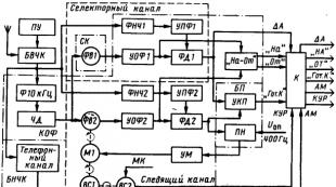
The ground part of the RMS consists of two radio beacons - localizer (LOB) And glide slope radio beacon (GRM), which emit two oblique beams (equal-signal zones) in the vertical and horizontal planes. The intersection of these zones forms the approach path. Aircraft receiving devices determine the position of the aircraft relative to this trajectory and issue control signals to PKP-1 flight control device(in other words, on the artificial horizon) and planning and navigation device PNP-1(in other words, to the course indicator).

If the frequency is set correctly, then when approaching the runway the pilot will see two moving lines on the large attitude indicator - a vertical course command arrow And horizontal glide slope command arrow, as well as two triangular indices indicating the position of the aircraft relative to the calculated trajectory.
Wing mechanization
Extended flaps and slats.

Extended slats.
Wing mechanization- a set of devices on the wing of an aircraft designed to regulate its load-bearing properties. Mechanization includes flaps, slats, spoilers, spoilers, flaperons, active boundary layer control systems, etc.
Flaps
Flaps- deflectable surfaces symmetrically located on the trailing edge of the wing. The flaps in the retracted state are a continuation of the wing surface, while in the extended state they can move away from it with the formation of cracks. They are used to improve the load-bearing capacity of the wing during takeoff, climb, descent and landing, as well as when flying at low speeds. There are a large number of types of flap designs:
The principle of operation of flaps is that when they are extended, the curvature of the profile increases and (in the case of retractable flaps, which are also called Fowler flaps) the surface area of the wing, therefore, the lift force increases. The increased lift allows aircraft to fly without stalling at lower speeds. Thus, extending the flaps is an effective way to reduce takeoff and landing speeds. The second consequence of flap extension is an increase in aerodynamic drag. If during landing the increased drag helps to slow down the aircraft, then during takeoff the additional drag takes away part of the engine thrust. Therefore, during takeoff, the flaps are always extended at a smaller angle than during landing. The third consequence of flap release is longitudinal rebalancing of the aircraft due to the occurrence of additional longitudinal moment. This complicates the control of the aircraft (on many modern aircraft, the diving moment when the flaps are extended is compensated by moving the stabilizer to a certain negative angle). Flaps that form profiled slits during release are called slotted. Flaps can consist of several sections, forming several slits (usually from one to three).
For example, the domestic Tu-154M uses double-slot flaps, and the Tu-154B uses three-slot flaps. The presence of a gap allows the flow to flow from an area of high pressure (the lower surface of the wing) to an area of low pressure (the upper surface of the wing). The slots are profiled so that the stream flowing from them is directed tangentially to the upper surface, and the cross-section of the slot should gradually narrow to increase the flow speed. After passing through the slot, the high-energy jet interacts with the sluggish boundary layer and prevents the formation of vortices and flow separation. This event makes it possible to “push back” the flow stall on the upper surface of the wing to higher angles of attack and higher lift force values.
Flaperons
Flaperons, or “hovering ailerons” - ailerons that can also perform the function of flaps when they are deflected down in phase. Widely used in ultra-light aircraft and radio-controlled model aircraft when flying at low speeds, as well as during takeoff and landing. Sometimes used on heavier aircraft (for example, Su-27). The main advantage of flaperons is their ease of implementation on the basis of existing ailerons and servos.
Slats
Slats- deflectable surfaces installed on the leading edge of the wing. When deflected, they form a gap similar to that of slotted flaps. Slats that do not form a gap are called deflectable leading edges. As a rule, the slats are automatically deflected simultaneously with the flaps, but can also be controlled independently.
In general, the effect of slats is to increase the permissible angle of attack, that is, flow separation from the upper surface of the wing occurs at a higher angle of attack.
In addition to simple ones, there are so-called adaptive slats. Adaptive slats automatically deflect to ensure optimal wing aerodynamic performance throughout the flight. Roll control is also ensured at high angles of attack using asynchronous control of adaptive slats.
Interceptors

Release of the left aileron spoiler when parrying a right roll
Interceptors (spoilers)- surfaces on the upper surface of the wing that are deflected or released into the flow, which increase aerodynamic drag and reduce lift. Therefore, spoilers are also called direct lift control elements.
Depending on the purpose and surface area of the console, its location on the wing, etc., interceptors are divided into:
Aileron spoilers
Aileron spoilers They are an addition to the ailerons and are used mainly for roll control. They deviate asymmetrically. For example, on a Tu-154, when the left aileron is deflected upward by an angle of up to 20°, the aileron-interceptor on the same console automatically deflects upward by an angle of up to 45°. As a result, the lift on the left wing console decreases, and the plane rolls to the left.
For some aircraft, aileron spoilers may be the main (or backup) roll control element.
Spoilers

Spoilers released
Spoilers (multifunctional spoilers)- lift dampers.
The symmetrical activation of spoilers on both wing consoles leads to a sharp decrease in lift and braking of the aircraft. After release, the aircraft balances at a higher angle of attack, begins to slow down due to increased drag, and descends smoothly. It is possible to change the vertical speed without changing the pitch angle. That is, when released simultaneously, the spoilers are used as air brakes.
Interceptors are also actively used to dampen lift after landing or during an aborted takeoff and to increase drag. It should be noted that they do not so much dampen the speed directly as they reduce the lift of the wing, which leads to an increase in the load on the wheels and improved traction of the wheels with the surface. Thanks to this, after releasing the internal spoilers, you can proceed to braking using the wheels.
see also
- Rotary slat - a propulsion device based on a slat
- Vibrating slat - slat-based propulsion
- Ailerons are rudders that control the roll of an aircraft.
- Aerodynamics of the Boeing 737
Notes
Wikimedia Foundation. 2010.
See what “Wing mechanization” is in other dictionaries:
A set of devices in the front and (or) rear parts of the wing to change its aerodynamic characteristics. The operation of all airfoil elements is based on controlling the boundary layer on the wing surface and (or) changing the curvature of the profile. M. k.... ... Encyclopedia of technology
A set of devices that change the lift and drag of an aircraft wing. MK reduces the speed of landing of an aircraft, and during takeoff it facilitates its lifting off the surface of the earth. Depending on the type of M. lifting... ... Great Soviet Encyclopedia
wing mechanization Encyclopedia "Aviation"
wing mechanization- Rice. 1. Scheme of mechanization of the front part of the wing. wing mechanization a set of devices in the front and (or) rear parts of the wing to change its aerodynamic characteristics. The work of all elements of the M.K. is based on the management of the border... ... Encyclopedia "Aviation"
wing mechanization- Rice. 1. Scheme of mechanization of the front part of the wing. wing mechanization a set of devices in the front and (or) rear parts of the wing to change its aerodynamic characteristics. The work of all elements of the M.K. is based on the management of the border... ... Encyclopedia "Aviation"
wing mechanization- Rice. 1. Scheme of mechanization of the front part of the wing. wing mechanization a set of devices in the front and (or) rear parts of the wing to change its aerodynamic characteristics. The work of all elements of the M.K. is based on the management of the border... ... Encyclopedia "Aviation"
Wing mechanization- devices (slats, flaps, flaps, etc.) for changing the aerodynamic characteristics of the wing in order to reduce the landing speed (take-off), take-off run (run), as well as improve the maneuverability of the aircraft in flight, etc.... Glossary of military terms
Encyclopedia "Aviation"
wing power mechanization- Rice. 1. Energy mechanization of the wing. energy mechanization of the wing devices for increasing the lifting force of the wing, the principle of operation of which is based on the use of energy from the aircraft engines or additional... ... Encyclopedia "Aviation"
Devices for increasing wing lift, the operating principle of which is based on the use of energy from aircraft engines or additional power sources. E.m.c. is used to improve the takeoff, landing and maneuvering characteristics of an aircraft,... ... Encyclopedia of technology
It consists of a whole set of movable elements that allow adjustment and control of the flight of the device. The complete set of wing elements consists of flaps, spoilers, slats, spoilers and flaperons.
Flaps are profiled deflectable surfaces that are located symmetrically to the trailing edge of each wing. When retracted, they act as an extension of the wing. When released, they move away from the main part of the wing to form a gap.
They significantly improve the load-bearing characteristics of the wing when lifting off from the runway, as well as when the airliner is climbing and landing. They provide excellent lift and control of the vehicle at fairly low flight speeds. Throughout the history of aircraft manufacturing, many models and modifications of this part have been developed and implemented.
Flaps are an integral part of the wing. When they are released, the curvature of the wing profile increases significantly. Accordingly, the load-bearing capacity of the aircraft's wings increases. This ability allows aircraft to move at low speeds without stalling. The operation of the flaps allows you to significantly reduce the speed of landing and takeoff without danger to the aircraft.
Due to the extension of the flaps, aerodynamic drag increases. This is very convenient when landing, as they create more drag, which allows you to reduce your flight speed. During takeoff, such drag is a little inappropriate and takes away some of the engines' thrust. Accordingly, when landing, the flaps are fully extended, and during takeoff, at a small angle, in order to facilitate the operation of the power plant.
Due to the additional longitudinal moment of flight, overbalance occurs. This, of course, complicates the work of pilots in controlling and maintaining the normal attitude of the aircraft. In modern aviation, most aircraft are equipped with slotted flaps, which can consist of several sections; accordingly, they form several slits. The presence of gaps between the flap sections allows high-pressure air on top of the wing to flow into the low-pressure area below the wing.

The structure of the flaps ensures that the air stream flows tangentially relative to the top of the surface. The cross-section of the slot narrows towards the edges, this allows the flow rate to increase. Having passed the flap slots, the jet with high energy levels interacts with the layer of air under the wing, thereby eliminating the occurrence of turbulence. The flaps can be operated at the pilot's command or in automatic mode. Cleaning and extension of elements occurs due to electric, pneumatic or hydraulic drives. The first aircraft in our country on which flaps were installed was manufactured back in the 20s of the last century; it was an R-5 type aircraft. These wing elements began to be used more widely in the 30s, namely with the advent of machines with a monoplane body.
Main types of flaps
Rotary or simple flap. The most elementary in its design, it allows you to increase the lifting force of the vehicle by changing the curvature of the wing profile. This design allows you to increase air pressure from below the wing. Of course, this type is significantly inferior in efficiency to the panel type.
Shield type flaps. They can be retractable or simple. As for simple flaps, they are represented by a controllable surface that is in the retracted position, while they fit tightly to the bottom of the wing. By deviating, they create a rarefied pressure zone on top of the wing. Accordingly, the upper boundary layer flows down. Pressure increases from below, which creates additional lift. All this contributes to lift-off and climb at much lower speeds. Speaking about retractable shield flaps, it is worth noting that, in addition to deflection, they have the ability to extend backwards. This in turn increases their efficiency. This design allows you to increase lifting force by 60%. They are still used today on light aircraft.
Slotted flap type. They get their name due to the formation of a gap when they are deflected. A flow of air passes through it, which is directed with great force into the low pressure zone formed under the wing of the aircraft. At the same time, the flow direction is well thought out and does not allow flow disruption. The gap formed by the flap narrows towards the edge, which allows the passing flow to receive maximum energy. On modern aircraft, slotted flaps are installed, consisting of several sections, which can form from one to three slits. Using such flaps, the aircraft gains lift up to 90%.
The Flaurea flap has a retractable design. The difference is the ability to extend not only backwards, but also downwards. This significantly increases the overall curvature of the aircraft's wing profile. This extension can create up to three slits. The increase in lifting force reaches 100%.
Junkers flap. It is made like a slotted flap, only its upper part serves as an aileron. This allows for better control of the aircraft's roll. The inner two parts of the structure perform the work of the flap. This design was used in the Ju 87 attack aircraft.
Jungmann design flap. This design was first installed on a British-made carrier-based fighter such as the Firefly. By increasing the wing area and lifting force, they were planned to be used at all stages of the flight.
Goudge flap. The main objective of the design was to reduce speed during landing. In addition to changing the curvature, they also increased the area of the wing itself. This design made it possible to reduce the takeoff speed during takeoff. The inventor of this scheme is the English designer A. Goudge, who worked hard on aerodynamic schemes. They were equipped with the Short Stirling aircraft in 1936.
Blow-type flap. This design had a high-quality control system for the upper boundary layer. Blowing made it possible to significantly improve the characteristics of the device during landing. This design made it possible to ensure a high-quality overall flow around the wings. It is known that the boundary layer arises due to the occurrence of viscous friction of the air flow on the surface of the aircraft, while the flow velocity near the skin is zero. It is through the system of influence on this layer that the flow can be prevented from stalling.
Jet flap. It provides a powerful air flow in the plane of the wing, which flows out from the lower surface. This changes the streamlining and increases the lift of the device. As lifting force increases, more air flow is required. It is worth noting that the effectiveness of this design decreases significantly as the overall wing aspect ratio decreases. Near the ground, such flaps do not justify the designers' calculations. Because of this, they are not widely used in the aircraft industry.
The stationary Gurney flap is represented by a perpendicular plane, which is installed at the end of the wings.
The Coandé flap has a constant surface curvature. It is designed for the so-called Coandé effect - when the jet sticks to the surface of the wing, which is subject to blowing.
Designers around the world are still working fruitfully to improve the aerodynamic properties of aircraft.
Many of those who flew on passenger airliners and sat at the window near the wing of the plane saw how the wing seemed to “straighten” before takeoff (or landing). New planes “crawl out” from its trailing edge, slightly curving downwards. And during the run after landing, something similar to almost vertical flaps rises on the upper surface of the wing. These are the elements of wing mechanization.
Man has always strived to fly faster. And he succeeded :) “Higher, faster – always!” Speed is an object of aspiration and a stumbling block. Fast at altitude is good. But it’s different during takeoff and landing. High takeoff speed is not needed. Until her plane (especially if it is a large, heavy airliner) takes off, no runway will be enough, plus there are limitations on the strength of the landing gear. Moreover, the landing speed should not be very high. Either the chassis will collapse or the crew will not be able to pilot it. And the mileage after landing will be quite big, where to get such large airfields :)
This is where the man’s ingenuity and cunning came in handy :) The solution was found, in general, without much difficulty. This is the take-off and landing mechanization of the wing.
Mechanization includes flaps, slats, spoilers, spoilers, flaperons, active boundary layer control systems, etc. For clarity, we present a well-known drawing:


Flaps are the first type of wing mechanization invented, and they are also the most effective.

The flaps are always located on the trailing edge of the wing and always go down, and, moreover, can be extended back. They help our aircraft improve the load-bearing capacity of the wing during takeoffs, landings, climbs and other maneuvers. In working language they act as a sail during takeoff and a parachute during landing))
Depending on the type of aircraft, different schemes are used:

Yak-40 landing with flaps extended:

SLATS
The next element of the wing mechanization is the slats. To expand the aircraft's ability to fly at high angles of attack (and therefore at lower speeds), slats were invented.
Conventional slotted slat in extended state:

You've probably seen how planes, after taking off from the runway, do not rise smoothly, but do so intensely, raising their noses quite sharply. This is just an airplane with working slats.
In design and principle of operation, slats are similar to slotted flaps, only they are naturally installed on the leading edge of the wing.
Tu-154 taxiing, with slats extended:

Slats and flaps usually work together. However, for different types of aircraft, specific modes of their separate operation are possible. For example, mid-air refueling.
That's probably all about the elements related to the concept of takeoff and landing wing mechanization. These elements allow the aircraft to feel confident during takeoff and landing and at the same time look quite impressive (interesting)
AILERONS
And now about the remaining wing elements indicated in the figure at the beginning of the article. Ailerons.
I would not classify them as wing mechanization. These are the controls for lateral control of the aircraft, that is, control along the roll channel. They work differentially. On one wing up, on the other down. However, there is such a thing as flaperons, which are slightly “related” to ailerons and flaps. These are the so-called “hanging ailerons”. They can deviate not only in opposite directions, but, if necessary, in the same direction too. In this case, they act as flaps. They are not used often, mainly on light aircraft.

INTERCEPTERS
The next element is interceptors. These are flat elements on the upper surface of the wing that rise (deflect) into the flow. In this case, this flow is slowed down, as a result of which the pressure on the upper surface of the wing increases and then, of course, the lift of this wing decreases. Interceptors are also sometimes called direct lift control elements.
We brake with spoilers:

Depending on the purpose and surface area of the console, its location on the wing, etc., spoilers are divided into aileron spoilers and spoilers.
The effect of the spoilers is used during piloting and for braking. In the first case, they work (deflect) in conjunction with ailerons (those that deflect upward) and are called aileron-interceptors. Examples of aircraft with such controls are TU-154, B-737.
Boeing 737. The left aileron spoiler operates to eliminate right roll:

In the second case, the synchronous release of spoilers allows you to change the vertical speed of the aircraft without changing the pitch angle (that is, without lowering its nose). In this case, they act as air brakes and are called spoilers. SPOILERS are usually also used after landing, simultaneously with the reverse thrust (if, of course, there is one 🙂). Their main task in this case is to quickly reduce the lift of the wing and thereby press the wheels against the concrete so that they can effectively brake with the wheel brakes.
Spoilers released (landing):

WING TIPS
Wing tips serve to increase the effective span of the wing, reducing the drag created by the vortex breaking off the tip of the swept wing and, as a result, increasing the lift force at the tip of the wing. Also, the winglets allow you to increase the aspect ratio of the wing, while almost without changing its span.

The use of wingtips can improve the fuel efficiency of aircraft or the flight range of gliders. Currently, the same types of aircraft can have different winglets.

This is the wing mechanization in a nutshell. Exactly in brief. In fact, this topic is much broader.
If you want to show off your erudition in a narrow circle, know this! Most modern airplanes have ONE wing! And on the left and right these are half-Wings!))
But today I’m already occupying your attention too much. I think there's still more to come