Limit bar sign. Limit column. Damn.19. light indicator "lower pantograph"
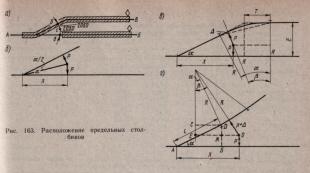
At sidings, passing points and stations, the tracks are limited by limit posts and signals. The limit columns indicate the place beyond which rolling stock cannot be installed on the track in the direction of the turnout. This ensures traffic safety. So, the tail of the train is on the way A- B must stand so that the train coming from A(or from B to A), one could easily take the path A - B(Fig. 163, A). This is possible if the distance b- With enough to pass along the way A- IN the widest carriage or locomotive, taking into account vibrations during movement. Distances b - With And With- d according to the PTE they are equal to 2050 mm, which corresponds to a distance between tracks of 4100 mm; on existing tracks, a distance of 3810 mm is allowed; on transfer tracks with a narrowed inter-track, limit posts are installed where the inter-track width is 3600 mm. With a car width of 3600 mm, the free gap for safe passage of cars will be 4100-3600 = 500 mm. If these minimum distances are observed, depending on the location of the converging paths, the distance from the center of the turnouts to the limit posts will be different:
the limit column is located between straight converging paths (Fig. 163, b)

Table 5
Distance in m from the center of the turnout to the limit column and signal (main cases) at stations equipped with electrical interlocking
|
Device |
Interpath, m |
Cross brand |
|||
|
Limit column | |||||
|
Traffic light on a mast without a ladder | |||||
|
Dwarf traffic light | |||||
Table 6
Distance from the center of the turnout to the limit post and traffic light (mast) on tracks not equipped with electrical centralization
|
Width between tracks, m |
Design and brand of cross |
Width between tracks, m |
|||||
|
Limit column |
Traffic light | ||||||
limit column of a wool switch (Fig. 160, a); output signals - at each track or group of tracks intended for the departure of a train, in front of the locomotive parking area. Signals located in between tracks are placed taking into account the size of the approaching buildings, mast traffic lights - at a distance of 2450 mm from the track axis. Distances to signals are calculated using the same formulas as to the limit columns (Tables 5 and 6).
When equipping switches and signals with electrical centralization, station tracks and necks are divided into isolated sections. Insulating joints are located at a distance of at least 3.5 m from the limit posts away from the station. Between these joints and the tail of the crosspiece it is necessary to lay non-standard rail houses. In order to be able to lay standard cuttings behind the tail of the crosspiece (minimum cutting is 6.25 m and, as an exception in difficult conditions, 4.5 m), the calculated distance between the limit column and the center of the switch is increased accordingly, while maintaining the specified useful track length.


output signal and limit column at the opposite end of the path (on the path 5 signal I 5 and the limit column at the turnout 15; on a way 2 signal H 2 and the limit column at the turnout 2) . The useful length of the double-acting track (main track I) differs in directions (for direction B - the distance between the limit column at the turnout 4, but not 2 and signal H 1 for the direction to A - between the limit column at the turnout 5 and signal N 1 ) ;
limit column and anti-hair turnout (path 7 - from the limit column at the turnout 19 to front frame rail joint arrows 14) ;
limit column and stop of a dead-end path (path 10, 8 And 9);
anti-hair arrow or signal and dead-end path stop (exhaust path 4 - from shunting signal M 4 all the way, if there is no signal - from the front joint of the frame rail at the turnout 7 all the way).
To determine the need for superstructure materials, calculate full length station tracks. It is important not to miss any elements of the path and not to count them twice. Counting is usually carried out along the track axes from the centers of the turnouts. Since turnouts in sets are supplied separately, after calculating the total length of the station tracks, the total length of all turnouts is subtracted from it. Main paths are not included in the calculation. We will show how to calculate the total length of station tracks in Fig. 166:
Separately calculate the length of the ramps 11 -3,1 -7 and 17 -21. The access road is taken into account if its construction is included in the project. If rails of different types are laid at a station, the total length is calculated for each type separately.
The useful length of receiving and departure tracks for freight traffic (1250, 1050 and 850 m) is taken in accordance with the length of trains planned for a given line in the tenth year of operation, taking into account the unified length of trains on neighboring lines. On lines with high traffic load, with an appropriate feasibility study, receiving and departure tracks can be adopted with a larger useful length (one and a half or double). This will make it possible to organize the driving of long trains and connected trains. Useful track lengths for the reception and departure of various types of transfer trains, freight fronts, etc. are established depending on the freight turnover, technological
whom the work process and local conditions. The useful length of tracks intended to carry only passenger trains with parking must correspond to the longest length of the latter accepted for use in the fifth year of operation, and the length of passenger platforms up to 500 m (and those serving only suburban traffic - 300 m). The useful length of marshalling tracks for the accumulation and formation of single-group trains, as well as the connection of parts of group trains, is taken depending on the length of their trains, and at marshalling stations it is recommended to increase the length of the tracks by at least 10%. The useful length of safety dead ends is at least 50 m, the main exhaust tracks at district and marshalling stations are equal to the full length of the freight train, and at intermediate stations - at least half of it (in the first stage - at least 200 m).
Read also:
|
Answer.
A track sign is a permanent indicator of the profile and length of railway lines.
Signal sign - a conventional visible sign (a limit column, a sign indicating the boundaries of a railway station, blowing a whistle, turning off and on the current, etc.), with the help of which an order is given to a certain category of railway transport workers
Special track signs - boundaries of the railway right-of-way, arrow number indicator, passenger building axis sign, signs on linear track buildings, benchmarks of the beginning and end of circular curves, as well as the beginning, middle and end of transition curves, hidden structures of the roadbed, the highest water horizon and maximum wave height
Signal signs are installed, respectively, by the owner of the infrastructure, the owner of the non-public railway track on the right side in the direction of movement, and track signs - on the right side according to the number of kilometers at a distance of at least 3100 mm from the axis of the outer railway track.
In excavations (except rocky ones) and at the exits from them, track and signal signs are installed, respectively, by the owner of the infrastructure, the owner of the non-public railway track outside the ditches and chutes on the field side. In heavily drifted excavations and at the exits from them (within up to 100 m), these signs are installed at a distance of at least 5700 mm from the axis of the outer railway track. The list of such excavations is established, respectively, by the owner of the infrastructure, the owner of the non-public railway tracks. In electrified areas, signal and route signs can be installed on contact network supports, except for those supports on which traffic light heads, complete transformer substations, contact network disconnectors and arresters are installed.
Limit columns are installed in the middle of the intertrack in the place where the distance between the axes of converging railway tracks is 4100 mm. On existing station railway tracks, which are not used by railway rolling stock built to gauge T, it is allowed to maintain a distance of 3810 mm. On transshipment railway tracks with a narrowed inter-track, limit posts are installed in the place where the width of the inter-track reaches 3600 mm.
On curved sections of the railway track, these distances must be increased in accordance with the rules and regulations.
Signal, wayfinding and special waymarks must comply with the rules and regulations.
13. Installation and purpose of the limit column.
Answer.
Limit bars indicate the boundary within which rolling stock can be located on a given track without violating the safety of traffic on the adjacent track.
Limit posts for station tracks (except for receiving and departure ones equipped with electric rail circuits) are installed in the middle of the track in the place where the distance between the axes of the tracks diverging from the center of the switch is equal to 4100 mm . On existing station tracks, which are not used by rolling stock built according to gauge T, it is allowed to keep this distance equal until reconstruction 3810 mm.
Setting limit bars carried out behind the turnout cross in a sharp corner. Limit column determines the gauge of the railway track or indicates the boundary within which rolling stock can be located on a given track without interfering with the safety of traffic on the adjacent track.
Limit posts for station tracks (except for receiving and departure ones equipped with electric rail circuits) are installed in the middle of the track in the place where the distance between the axes of the tracks diverging from the center of the switch is equal to 4.1 m(from the limit column to the axis of the straight path R= 2.05). On existing station tracks, which are not used by rolling stock built to gauge T, it is permitted to install limit posts at a distance of 3.81 m (before reconstruction).
The distance from the translation center to the limit column installed between two straight paths diverging in different directions will be R·ctg(α/2) (or rounded 4.1ctg α), but after branching the paths most often run parallel to each other (Fig. 1, a). In this case, the distance to the limit column depends not only on the brand of the translation cross, but also on the width of the interpath and the radius of the curve.
Rice. 1 - Schemes for installing limit columns
The distance from the limit column to the axis of the path in the curve should be R+ ∆, where ∆ is the increase in the overall distance to structures located on the inside of the curves (with R= 200 m it is equal to 0.18 m, with R= 300 m - 0.12 m). The value of the angle β at e > 2R+ ∆ is determined from the equality
![]()
Distance from translation center to limit column
The installation of limit columns when the turnout has a conversion curve (Fig. 1, b) is carried out on the basis of the following formulas:

where ∆ n is the increase in the overall distance to structures located on the outside of the curves.
When installing limit posts on receiving and departure tracks equipped with electric rail circuits, insulating joints must be placed at a distance of 3.5 m behind the limit post (taking into account the maximum length of the protruding part of the rolling stock in relation to the outer axis). In order to use standard cuttings (12.5 and 6.25 m) on the section of the track from the end of the cross to the insulating joint, it is recommended to slightly increase the distance from the center of the transfer to the limit column compared to the calculated dimensional conditions.
GOST 8442-65
Group D58
STATE STANDARD OF THE USSR UNION
TRAIL AND SIGNAL SIGNS OF RAILWAYS
Track and signal signs of rail roads
Date of introduction 1966-01-01
INTRODUCED by the Ministry of Railways
APPROVED AND ENTERED INTO EFFECT by the State Committee of Standards, Measures and Measuring Instruments of the USSR on April 17, 1965.
REISSUE (December 1982) with Amendments No. 1, 2, approved in April 1976, April 1981 (IUS 6 - 1976, 7 - 1981).
AMENDED Change No. 3, approved and put into effect by Resolution of the USSR State Committee for Product Quality Management and Standards dated 06.27.90 N 1906 from 01.01.91
Change No. 3 was made by the legal bureau "Code" according to the text of IUS No. 10, 1990
This standard applies to track and signal signs on 1520 (1524) mm and narrow gauge railways.
The standard does not apply to special signs for in-plant transport of industrial enterprises.
The standard takes into account the requirements of the Convention on Road Signs and Signals (1968) and the European Agreement supplementing the Convention on Road Signs and Signals.
The requirements established by this standard are mandatory.
I. SHAPE AND SIZES OF SIGNS
I. SHAPE AND SIZES OF SIGNS
The shape, dimensions of track and signal signs, the location of inscriptions, as well as the sizes of letters and numbers must correspond to those indicated in Figure 1-44.
1. TRAFFIC SIGNS
Damn.1. Kilometer sign
Kilometer sign
Damn.1
The sign is installed to sequentially count kilometers from Moscow on the main railway lines determined by the Ministry of Railways.
The serial numbers of kilometers must be shown on both sides of the plate. On one side is the number of the kilometer that ends before the sign, on the other - the number of the kilometer that begins after the sign.
The sign must be attached to the top of the post.
Damn.2
The sign is installed to sequentially count kilometers from the beginning of the railway or its line, the access road on other sections of the railways and access roads.
Damn.3. Picket sign
Picket sign
The serial numbers of the pickets must be depicted on two opposite sides of the post, perpendicular to the axis of the path. On one side of the post the number of the picket that ends in front of the sign is marked, on the opposite side - the number of the picket that begins behind the sign.
Damn.4. Incline sign
Incline sign
The first number on the sign must indicate the amount of ascent or descent on the section of the road following the sign; The numbers after the dash indicate the length of the path with this profile.
Signs must be installed perpendicular to the axis of the track.
A sign located perpendicular to the axis of the post must indicate the site; with an upward slope from the pillar - ascent, with a downward slope from the pillar - descent.
2. SPECIAL TRAVEL SIGNS
Damn.5. Railway right-of-way boundary sign
Railway right-of-way boundary sign
The plate (or the plane of the pillar on which the letters and images of the hammer and sickle are applied) must be installed parallel to the axis of the path.
Damn.6. Sign of the highest water horizon and maximum wave height
Sign of the highest water horizon and maximum wave height
The sign must contain numbers indicating the distance in meters from the bottom line of the ring:
upper - up to the maximum wave height;
the lower one - to the highest water horizon.
Damn.7. Signs of hidden subgrade structures
Signs of hidden subgrade structures
The sign must indicate:
in the first line - the symbol for the hidden structure of the roadbed;
in the second - the number of the structure;
in the third - PC and picket number;
in the fourth - the year the structure was built.
The sign (or the plane of the post on which the inscriptions are written) must be installed parallel to the axis of the track.
Signs are installed by relevant ministries and departments.
Damn.8. Picket signs
Picket signs;
benchmarks of the beginning and end of circular curves, the beginning, middle and end of transition curves; railroad right-of-way boundary signs, hidden subgrade signs made of stone and concrete
The inscriptions on these signs are applied according to drawings 3, 5 and 7.
The type of benchmarks for the beginning and end of circular curves, the beginning, middle and end of transition curves and the inscriptions on them are indicated in Figures 9 and 9a.
Damn.9. Benchmarks of the beginning and end of a circular curve (made of stone and concrete
Benchmarks of the beginning and end of a circular curve (made of stone and concrete)
The markers of circular curves indicate:
NCC - the beginning of a circular curve;
KKK - end of a circular curve;
PC - number of the previous picket plus the distance from it to the beginning (end) of the curve, m;
R - radius of the circular curve, m;
B - elevation of the outer rail, mm.
The following are indicated on the transition curves:
NPK - beginning of the transition curve;
CPC - end of the transition curve;
SPK - the middle of the transition curve;
O - elevation outlet, %.
In forest areas it is allowed to make them from wood.
Benchmarks are installed when they cannot be replaced by nearby permanent devices (contact network supports, artificial structures, etc.).
Devil.9a. Benchmarks of the beginning, middle and end of the transition curve (made of stone and concrete)
Benchmarks of the beginning, middle and end of the transition curve (made of stone and concrete)
Drawing 9a
(Introduced additionally, Amendment No. 2).
Signs on linear track buildings
On linear track buildings the following must be installed:
a) a sign indicating the kilometer on which the building is located.
The dimensions of the plate, as well as the location and size of the numbers on the sign must correspond to Figure 1;
b) a sign of the presence of a telephone in this building (see drawing 10).
Damn.10
Damn.10
A sign indicating the kilometer on which the building is located must be installed on the linear track building on the side of the main track in the upper left corner at a distance of 0.3 or 0.5 m above the windows and 0.3 or 0.5 m from the edge of the building.
Under this sign there is a sign indicating the presence of a telephone.
Damn 11. Passenger building axis signs
Passenger building axis signs
The sign must contain letters indicating:
O - axis;
P - passenger;
Z - building.
The passenger building axis sign must be installed on the side of the main track at a height of 0.5 m above the top of the first floor windows.
Damn.12. Arrow number sign
Arrow number sign
A sign indicating the arrow number must be installed perpendicular to the axis of the track on the frame of the transfer mechanism. It is permissible to paint the pointer number directly on the frame of the transfer mechanism or on the housing of the pointer drive with centralized control.
3. WARNING SIGNS AT CROSS-CROSSINGS
A. BEWARE OF TRAIN signs
a) at an unguarded crossing (without barriers)
Drawing 13. (Excluded. Amendment No. 3).
Drawing 13a, 13b
The sign is installed when a road crosses one railway track.
Drawing 13a, b. (Introduced additionally, Amendment No. 1. Amended edition, Amendment No. 3).
Drawing 14. (Excluded, Amendment No. 3).
Drawing 14a, 14b
The sign is installed when a road crosses two or more railway tracks.
Signs must be installed perpendicular to the axis of the road.
Drawing 14a, b. (Introduced additionally, Amendment No. 1. Amended edition, Amendment No. 3).
Damn.15. (Deleted, Amendment No. 1).
Drawings 16, 16a, 17, 17a. (Excluded, Amendment No. 3).
4. SIGNAL SIGNS
A. Permanent signal signs
Damn 18. Sign "ATTENTION! - CURRENT CUT"
Sign "ATTENTION! - CURRENT CUT"
Damn.18*
____________________
* Drawing 18. Modified edition, Rev. N 3.
Damn.19. Light indicator "LOWER POWER COLLECTOR"
Light indicator "LOWER POWER COLLECTOR"
The sign must be installed perpendicular to the track axis on overhead contact line supports or individual masts.
(Changed edition, Amendment No. 1).
Damn.20. Sign "LIFT POWER COLLECTOR"
Devil.20*
___________________
* Drawing 20. Modified edition, Rev. N 3.
The sign must be installed perpendicular to the track axis on supports or overhead cables of the overhead contact line.
(Changed edition, Amendment No. 1).
Damn 21. Sign "LIMIT COLUMN"
Sign "LIMIT COLUMN"
Reinforced concrete column
Wooden post
_______________
* Drawing 21. Modified edition, Rev. N 3.
The limit post sign at the main and reception and departure tracks must be installed so that the reinforced concrete posts have an edge with retroreflectors, and the wooden posts have a hewn flat edge with retroreflectors facing the direction opposite to the turnout or blind intersection.
For reinforced concrete columns, on the faces adjacent to the reflectors, the numbers of the tracks between which the column is installed are indicated.
The wooden posts have special notches on which the track numbers are indicated.
The limit post sign at other station tracks must be installed so that the edge formed by the intersection of the faces of the post with the numbers printed on them (indicating the numbers of the corresponding station tracks) faces towards the turnout or blind intersection.
(Changed edition, Amendment No. 3).
Damn 22. (Deleted, Amendment No. 2).
Damn 23. "STATION BOUNDARY" sign
"STATION BOUNDARY" sign
The inscription "STATION BOUNDARY" must be placed on both sides of the sign.
(Changed edition, Amendment No. 3).
Damn.24. Sign "APPROACH ROAD BOUNDARY"
Sign "APPROACH ROAD BOUNDARY"
The sign must be installed perpendicular to the axis of the path.
Devil.24a. (Deleted, Amendment No. 2).
Damn.25. Signs "BEGINNING OF A DANGEROUS PLACE" and "END OF A DANGEROUS PLACE"
_________________
* Drawing 25. Modified edition, Rev. N 3.
Signs must be installed perpendicular to the axis of the path.
B. Permanent warning signs
Damn 26. Sign "C" for blowing the whistle
Sign "C" for blowing the whistle
Devil.26*
__________________
* Drawing 26. Modified edition, Rev. N 3.
The sign must be installed perpendicular to the axis of the path.
Damn 27. Signs "START OF PUSHING" and "END OF PUSHING"
Signs "START OF PUSHING" and "END OF PUSHING"
Damn.27
The sign must be installed perpendicular to the axis of the path.
Damn 28. Signs "CLOSE SIPHON" and "CLOSE BLOWER"
Signs "CLOSE SIPHON" and "CLOSE BLOWER"
The sign is installed in the area with steam traction.
The sign must be installed perpendicular to the axis of the path.
It is allowed to install these signs on one pole.
Damn.29. "LOCOMOTIVE STOP" sign
"LOCOMOTIVE STOP" sign
Damn.29
Damn.30. Sign "STOP FIRST CAR"
The sign must be installed on poles or nearest permanent structures perpendicular to the axis of the path.
Damn.31. Sign "TURN OFF CURRENT"
Devil.31*
______________________
* Drawing 31. Modified edition, Rev. N 3.
The sign must be installed perpendicular to the track axis on supports or overhead cables of the overhead contact line.
Damn.32. Sign "TURN ON THE CURRENT ON THE ELECTRIC LOGO"
Sign "TURN ON THE CURRENT ON THE ELECTRIC LOGO"
Devil.32*
______________________
* Drawing 32. Modified edition, Rev. N 3.
The sign must be installed perpendicular to the track axis on supports or overhead cables of the overhead contact line.
Damn.33. Sign "TURN ON THE CURRENT ON THE ELECTRIC TRAIN"
Damn.33*
______________________
* Drawing 33. Modified edition, Rev. N 3.
The sign must be installed perpendicular to the track axis on supports or overhead cables of the overhead contact line.
The sizes and colors of both plates are the same.
(Changed edition, Amendment No. 2).
Damn.34. "END OF CABLE" sign
"END OF CABLE" sign
Damn.34*
______________________
* Drawing 34. Modified edition, Rev. N 3.
The sign must be installed perpendicular to the track axis on supports or overhead cables of the overhead contact line.
The letters shown on the plate may be cut out.
Damn.35. Signs "TRANSITION TO THE LATERAL CONTACT NETWORK" and "TRANSITION TO THE CENTRAL CONTACT NETWORK"
Signs "TRANSITION TO THE SIDE CONTACT NETWORK" and "TRANSITION TO THE CENTRAL
CONTACT NETWORK"
Damn.35
The sign must be installed perpendicular to the axis of the path.
These signs are not installed on the railways of the Ministry of Railways.
B. Temporary signal signs
Damn.36. Sign "PREPARE TO LOWER THE CURRENT COLLECTOR"
Sign "PREPARE TO LOWER THE CURRENT COLLECTOR"
Damn.36*
______________________
* Drawing 36. Modified edition, Rev. N 3.
The sign must be installed perpendicular to the track axis on supports or overhead cables of the overhead contact line.
(Changed edition, Amendment No. 1).
Damn.37. "LOWER POWER COLLECTOR" sign
"LOWER POWER COLLECTOR" sign
Damn.37*
______________________
* Drawing 37. Modified edition, Rev. N 3.
The sign must be installed perpendicular to the track axis on supports or overhead cables of the overhead contact line.
(Changed edition, Amendment No. 1).
Damn.38. Sign "LIFT POWER COLLECTOR"
Sign "LIFT POWER COLLECTOR"
______________________
* Drawing 38. Modified edition, Rev. N 3.
The sign must be installed perpendicular to the track axis on supports or overhead cables of the overhead contact line.
(Changed edition, Amendment No. 1).
Damn.39. "PREPARE TO RAISED KNIFE AND CLOSED WINGS" sign
"PREPARE TO RAISED KNIFE AND CLOSED WINGS" sign
Damn.39*
______________________
* Drawing 39. Modified edition, Rev. N 3.
The sign is installed perpendicular to the track axis in front of the “Knife Raise, Wings Closed” sign (Figures 40 and 41) in areas where high-speed snowplows operate.
"KNIFE RAISED, WINGS CLOSED" sign
The sign is installed perpendicular to the axis of the path:
a) in the presence of one obstacle;
Damn.42. Sign "KNIFE LOWER, WINGS OPEN"
Sign "KNIFE LOWER, WINGS OPEN"
Damn.42*
______________________
* Drawing 42. Modified edition, Rev. N 3.
The sign is installed perpendicular to the axis of the path.
The signs indicated in Fig. 40-42, at the customer’s request, can be produced without retroreflectors.
(Changed edition, Amendment No. 3).
D. Portable signal signs
Damn.43. Signs "BEGINNING OF A DANGEROUS PLACE" and "END OF A DANGEROUS PLACE"
Signs "BEGINNING OF A DANGEROUS PLACE" and "END OF A DANGEROUS PLACE"
______________________
* Drawing 43. Modified edition, Rev. N 3.
Signs must be mounted on poles perpendicular to the axis of the track.
The “End of a Dangerous Place” sign is placed on the reverse side of the “Start of a Dangerous Place” sign.
At the customer's request, signs can be produced without reflectors.
(Changed edition, Amendment No. 1,).
Damn.44. Sign "C" for blowing the whistle
Sign "C" for blowing the whistle
The sign must be attached to a pole perpendicular to the axis of the path.
II. TECHNICAL REQUIREMENTS
1. Signs must be manufactured in accordance with the requirements of this standard according to the drawings of the Ministry of Railways and GOST 10807-78 regarding technical requirements for signs according to drawings 13b, 14b.
(Changed edition, Amendment No. 1,).
2. The shape and dimensions of pillars (poles) for wayfinding and signal signs, as well as the method of attaching signs to them, are established according to the drawings of the Ministry of Railways.
3. Sign boards must be of durable and rigid construction.
4. Sign plates must be enameled or painted, except for signs according to drawings 13b, 14b.
Enameled plates must be made of pickled steel sheet in accordance with GOST 19904-74, sheet thickness from 0.8 to 1 mm; painted - from thin sheet steel in accordance with GOST 19903-74 or GOST 19904-74, sheet thickness from 0.9 to 2 mm, or from other materials with the necessary strength and resistance to atmospheric influences.
(Changed edition, Amendment No. 1,).
5. The pillars must be made of reinforced concrete. In forested areas, poles may be made of wood. It is allowed to use other materials (except metal) for the manufacture of poles that have the necessary strength and appropriate durability.
On electrified sections, signal and track signs “Attention! - current divider”, sign “Lower pantograph”, “Raise pantograph”, “Station boundary”, “Conductor”, sign “C” for blowing a whistle, “Start of pushing”, “End of pushing” ", "Turn off the current", "Turn on the current on the electric locomotive", "Turn on the current on the electric train", incline indicators - can be installed on overhead contact line supports (except for the supports on which traffic light heads and contact line disconnectors are installed).
(Changed edition, Amendment No. 1, 2).
6. Track and signal signs must be installed in accordance with the Rules for the Technical Operation of Railways of the USSR and the Instructions for Signaling on Railways of the USSR.
7. On narrow gauge railways, the distance from the ground or the level of the top of the rail head to the bottom edge of the sign plate can be changed by agreement between the ministries operating the roads, depending on the type of rolling stock in use.
8. The surface of the signs must be cleaned before painting. Painting is carried out over the ground in two layers with oil paints in accordance with GOST 8292-85 or pentaphthalic enamels in accordance with GOST 6465-76. The coloring should be even, without drips, wrinkles, stains and should not peel off.
(Changed edition, Amendment No. 3).
9. Inscriptions on signs or the edges of pillars are applied with black paints on a white background.
On wooden pillars of a railway right-of-way boundary sign, letters and an image of a hammer and sickle may be applied by burning.
(Changed edition, Amendment No. 1).
10. Sign plates on the front side are painted: according to drawings 1, 2, 4, 10, 11, 12, 23, 24, 28, 34 - white, the remaining signs - in the order indicated on the drawings. The reverse side of the plates is painted black.
(Changed edition, Amendment No. 1, 2,).
11. Columns must be painted gray, except for the lower part of the pillar - from ground level to a height of 250 mm, as well as the upper pointed part, which are painted black.
The text of the document is verified according to:
official publication
M.: Standards Publishing House, 1983
Revision of the document taking into account
changes and additions prepared
JSC "Kodeks"
Paths at separate points are limited by limit posts and traffic lights. A limit column is installed between converging tracks and indicates the boundary of the track beyond which no parts of the rolling stock should go. Rolling stock located within the track, limited by the limit posts, should not violate the clearances for movement along the adjacent track. The limit column is installed in the middle of the intertrack in the place where its width reaches 4.10 m between the axes of adjacent tracks. Accordingly, to install a limit column, it is necessary to ensure a distance of not 2.05 from the axis of each path to the vertical axis of the limit column.
intermediate station switch
For a 1/11 grade turnout, the distance from the center of the turnout to the limit column is 46.86 m.
The placement of traffic lights is one of the most important factors in the design of an intermediate station. Depending on the track development of the station, track specialization and operating technology, the following signals are installed at the station:
Entrance – enclosing the station from the side of the tracks;
Weekends - allowing or prohibiting the train to go on a stretch;
Route - allowing or prohibiting the train to proceed from one area of the station to another;
Maneuvering – allowing or prohibiting maneuvers.
Entrance traffic lights are installed in front of the entrance switch, at a distance of 50 m for diesel traction, and at least 300 m for electric traction. This distance is measured from the beginning of the points when laying the turnout anti-wool and from the limit column - if the turnout is made of wool. For given conditions, entrance traffic lights are located.
H at a distance of 50m in front of switch 2, taking into account the distance from the beginning of the points to the center of the switch:
Lch=50+11.25=61.25m;
Traffic light N:
Ln=50+12.42=62.42m.
When installing exit, route and shunting traffic lights, there are three methods depending on the installation location.
1. The traffic light is located in the same inter-path with the limit post fencing the path. In this case, the traffic light is located in the place where the width between the tracks is sufficient for its installation. This width depends on the design of the traffic light and, accordingly, its overall dimensions. Thus, the largest track-to-path width of 5.2 m is required for installing mast-mounted traffic lights on reinforced concrete or metal masts with stairs. The smallest width – 4.2 m – for installing a dwarf single traffic light. For practical purposes, the signal distance is taken lsign=56m according to the recommendations. The following traffic lights are installed using this method: Ch3, m8, m6, N4, Chm2, Chm4.
2. The traffic light is located at different interpaths with a limit column. limiting the length of the path enclosed by a traffic light. In this case, the traffic light is located in an alignment with an iso-joint, i.e. at a distance of 3.5 m from the limit post towards the track. Traffic lights are installed in this way: Ch1a, Nm3, m3, m10, m12, m4, m5, HI, N2.
3. The traffic light is installed in front of the turnout switch in the alignment with the joint of the frame rail, i.e. at a distance a from the center of the turnout. Traffic lights are located at a distance of Chm1-15.19m from TsSP 15; Nm1a - 14.02 m from DSP 7; m1 and m2 – 15.42 from DSP 3 and 6, respectively.