Pulse width modulation. PWM and PWM - what is it? PWM DC Voltage Regulators
A simple solution for your task!
Are available
Buy in bulkThe module is built on the basis of a powerful IRF2204 power switch with an operating current of up to 210A, and is designed to adjust the brightness of incandescent lamps, LED strips and the rotation speed of electric motors with a voltage of 6-30V.
It will be useful for adjusting the brightness of daytime running lights and will be indispensable for adjusting the speed of the stove, as well as as a speed regulator for an inflatable boat with an electric motor.
Adjusting the PWM control frequency will completely remove the hum of the motor windings, and the built-in protection will limit excess operating current.
Specifications
Peculiarities
- Compact size
- Wide range of smooth adjustment of PWM frequency - 300-10000Hz.
- Wide operating voltage range 6-30V
- Possibility of limiting operating current.
- Reverse polarity protection.
- Built on the powerful IRF2204 field switch
- It is possible to strengthen the power switch.
Additional Information
When the current is more than 5A, it is necessary to install a radiator. With a maximum current of 80A, the radiator area should be at least 600 cm2.
Articles
Contents of delivery
- Module - 1 pc.
- Instructions - 1 pc.
What is required for assembly
- To connect you will need: wire, screwdriver, side cutters.
Preparation for use
- Connect a 12V incandescent lamp to the OUT terminal.
- Apply 12V power to the IN terminal
- Rotate the variable resistor. When rotating, the brightness of the lamp should change.
- Check completed. Enjoy your use.
terms of Use
- Temperature -30C to +50C. Relative humidity 20-80% without condensation.
Precautionary measures
- Do not exceed the maximum permissible supply voltage of the module.
- Do not exceed the maximum permissible load power.
- Failure to comply with these requirements may result in device failure.
Questions and answers
- Good afternoon. Question about MP4511 PWM power regulator 6-35V 80A The task is to assemble an electric scooter and an electric car for a child. To do this, there is a 90 W 24 V 7 A motor for the scooter and a 110 W motor from the Gas stove at 15 A 12 V and a battery. Please confirm if I understood correctly. Will this device be enough to regulate the speed?! because On homemade sites, everyone orders Chinese controllers, but no one assembles anything using this device. Or something else will need to be included in the circuit. I also ask you to tell me the cost of delivery to Orenburg, receipt at the post office?! or a transport company to the addressee?! Thank you.
- Hello, Victor! MP4511 is a good choice, this module will work with your motor without any additional devices. Regarding delivery: we work with the SPSR service, the cost of delivery to your city is calculated after placing the order.
- Is it possible to order 12(24)-60V 80A???
- Vladimir, unfortunately, we do not have a module with such parameters for sale.
- Hello. I want to use this device to smoothly regulate the speed of a children's electric car, please tell me if it is possible to use an electronic pedal from the Priora with it (instead of a trimming resistor). Is there a smaller alternative to this pedal?
- Hello! I don’t know on what principle the Priora’s electronic pedal works. If there is a variable resistor with a resistance of 100...500 kOhm, then it will do.
- Good afternoon. I bought an MP4511 80a module. I lay idle for six months, but today I needed it. It is necessary to reduce the voltage from the screwdriver battery from 22 to 18 volts. I connect the battery and at the regulator input I see a voltage of 6.7 volts. load is disconnected. To test the load, I connect a 12 volt 5 watt lamp, the output voltage is no more than 2.3 volts. There is no scheme. Where to dig. Can you send me the diagram? Regards, Alexey.
- Check for installed jumpers. And the quality of soldering of all components.
- Hello. I want to use this module in a car. To use this PWM regulator after replacing the light bulbs with LEDs (connect to the old resistor 6...12V). Do I need to change the basic scheme additionally or leave everything as is?
- The module is not suitable for your task. Because the adjustment is made via the -12V circuit
- Is it possible to connect electric? boat motor ECO MOTOR PRO NISSAMARAN 36, if yes, then how to do it. Do you need a shunt, where to get it and how to eliminate the engine whistling if there is one. Is it necessary to install a power diode in parallel with the motor and which one is better? The speed is adjusted from 0?
- Can. There is no need to install a SHUNT. Install a jumper in its place. Set the generator PWM frequency to Hi. If the residual whistling of the windings interferes, try raising the PWM generator frequency to 20 KHz. To do this, change the value of resistor R1 to 510 Ohm, R5 to 10 kOhm, R8 to 4.7 kOhm. To facilitate the operation of the power switch, we recommend installing an additional one in parallel; there is a space provided on the board and designated as VT2. Power switches must be installed on a radiator with an area of at least 1000 cm2..jpg
- I received a power regulator, please tell me how to make a radiator if there are two elements through which heat should be removed on the board, and not one, as in the picture, and there is VOLTAGE between them! That is, I won’t be able to connect them to one radiator, because there will be a short circuit, and two radiators for each won’t work, because the distance between them is 1 mm!!!
- The elements must be installed on the radiator through a thermal transfer plate. In some cases, the VD2 element, which has two terminals, does not require installation on a radiator. Check if it is not heating up, just bend it away from the radiator.
- What kind of radiator is needed? Maximum current 5A.
- Sl-01H will be optimal https://site/shop/1920368
- Is there a box for it?
- There is no special case for the device. A universal case can be selected here https://site/shop/cases
- Hello! I wanted to buy PWM 4511 price 1030 delivery 850 rub. why so expensive? Nalchik city, Kabardino-Balkarian Republic. Is there no way to send by mail?
- Good afternoon. To send by Russian Post Fill out all fields in the cart and select online payment. Only paid orders are delivered by Russian Post. Cash on delivery is not available!
- Good day. Tell me, this regulator can be used to adjust the heat of nichrome by connecting it to the outputs of the PC power supply. I accidentally bought a frequency regulator, it does not reduce the voltage)
- Can
- Hello, question about MP4511. I use chrome wire for adjustment. Powered by the computer's power supply. I connect the PWM minus, +12V from the output minus to the nichrome and the second end of the wire to the 5 V power supply. Everything works but the windings of the power supply transformer squeak. How can I remove this? It just doesn’t work from 5 V PWM. It has to be like this. Maybe you can rearrange the jumpers somehow?
- This is not always possible, since it directly depends on the characteristics of the transformer coils and the electric motor. However, winding noise can be removed or reduced using the PWM generator frequency control on the module.
- Hello! How can I prevent the fan from whistling when the speed decreases?
- This is not always possible, since it directly depends on the characteristics of the windings of the transformer and electric motor. However, you can try changing the value of resistor R1 to 510 Ohms, R5 to 10 kOhms, R8 to 4.7 kOhms.
- Will this regulator handle 500 watts and 37 volts?
- It will withstand 500W, but the voltage of 37V will be at the possible limit of the linear stabilizer microcircuit. What kind of microcircuit does it come across? If the parameter is underestimated, it may burn out.
- Good afternoon Tell me, is it possible to control this device via Arduino Nano via an analog output 0 - +5V, through a transistor, to change the polarity and by connecting it instead of a potentiometer?
- In theory it’s possible, you should try it.
When we come across an unfamiliar word or concept in some literature, we want to quickly find out its definition. Knowing precise definition You can further trace the scope and methods of application of the main character of a particular concept. Today we will take a closer look at such a concept as a PWM controller.
Shima concept
Before defining the mentioned phrase, you should find out or just remind yourself of the principle of heating the power components of a radio circuit. Their essence lies in the operation of several switching modes. All electrical power components in such radio circuits are always in two states. The first is open, and the second is revealed. What is the difference between these two conditions? In the first case, the component has zero current. In the second, the component has a zero voltage value. The end result of the interaction of electrical power components with the required voltage can be considered the receipt of a signal of the form that is needed according to the established rules.
A shim is a special modulator designed to control the opening time of a power switch. The time for opening the key is set taking into account the voltage received. Get perfect option processing of a signal is possible only if the signal has passed through all the necessary stages without difficulty before being converted. What are these stages and what does the formation of such a signal consist of?
Features of the PWM controller
![]() The process of creating shim signals is very difficult. To facilitate this process, special microcircuits were invented. It is the microcircuits involved in the formation of PWM signals that are called PWM controllers. Their existence In most cases helps to completely solve the problem with the formation of wide-pulse signals. To more easily understand the mission and significance of the shim controller, it is necessary to become familiar with the features of its structure. Today it is known that any PWM controller actively used in electronics has the following components:
The process of creating shim signals is very difficult. To facilitate this process, special microcircuits were invented. It is the microcircuits involved in the formation of PWM signals that are called PWM controllers. Their existence In most cases helps to completely solve the problem with the formation of wide-pulse signals. To more easily understand the mission and significance of the shim controller, it is necessary to become familiar with the features of its structure. Today it is known that any PWM controller actively used in electronics has the following components:
- Power output. Bears great responsibility for the electrical supply of all existing circuits. Often The power pin is confused with the power control pin. It is important to know that despite the similar words in the name, these two concepts have completely different characteristics. This will once again clearly prove your familiarity with the power control pin.
- Power control pin. This component of the microcircuit monitors the state of voltage indicators directly at the pin of the microcircuit. The main task of the power control output is to prevent the design level from being exceeded. There is one serious danger, namely voltage reduction at the exit. If the voltage is reduced, the transistors begin to open halfway. Due to incomplete opening, they heat up quickly and can ultimately fail quickly. That's why moderate tension- this is the key to long-term operation of transistors in PWM controllers.
- general exit. The third main element of the scheme has the shape of a leg. This leg, in turn, is connected to the common wire of the circuit, which is responsible for powering the entire system.
All three components are very important. If at least one of the elements fails for some reason, the performance of the entire microcircuit deteriorates noticeably or stops completely.
Chip management systems
It is important to know not only what PWM controller chips are made of, but also what types of systems themselves exist. Currently, there are two main widely available pulse modulation systems in which PWM control takes an active part. Here are some of their features:
But you can get the desired signal at the output using both software and hardware methods.
Hardware method. The signal is received in this way using a special timer, which is initially built into the digital system. Such a timer generates or facilitates the inclusion of pulses at certain stages of signal output.
Software method. In this case, signals are received by executing special software commands. The software method has more options than hardware. At the same time, using this method of receiving signals can take up a lot of memory.
What can we say about the “heart of the system”. The shim controller, which is actively used in digital modulators, has its advantages. It is worth remembering the following:
- Low cost.
- Stable work.
- High reliability.
- Possibility to save energy.
- high signal conversion efficiency.
 All of these advantages make the digital system more popular among consumers.
- Analog modulator. The operating principle of an analog modulator is fundamentally different from the operating principle of a digital one. The whole essence of the operation of such a modulator is to compare two signals. These signals differ in frequency order. The operational amplifier is the main element of the analog modulator, which is responsible for comparing signals. Comparison of signals is carried out at the output. The amplifier uses two signals as a comparison. The first is a high-frequency sawtooth voltage. The second signal is low frequency voltage. After comparison, rectangular pulses appear. The duration of the pulses directly depends on the modulating signal.
PWM controller in switching power supplies
Many electrical appliances today are equipped with special power supplies. These blocks help transform one type of voltage into another. IN Two devices take part in the energy conversion process:
- Impulse power block.
- analog transformer devices.
In this article we will pay more attention to the first device, since it is the one that uses the PWM controller.
Scheme of operation of a switching power supply
This device was born just a few decades ago. However, it has already become popular and in demand. Impulse power block consists of the following parts:
- Filter condensate.
- Key power transistor.
- A network rectifier consisting of several elements.
- Rectifier diodes of the output system.
- Power chokes. The choke helps correct the resulting voltage.
- Switching power supply. It is from here that the voltage is converted into a power circuit.
- Output voltage control circuits.
- Accumulative filter container;
- Optocoupler;
- Master oscillator.
- feedback circuits.
Knowing the composition of the pulse unit, you should familiarize yourself with the principle of its operation.
Operating principle of the pulse unit
![]() Operating principle of the pulse unit consists of delivering a stabilized supply voltage based on the principle of interaction between the elements of an inert system. Here are the step-by-step steps that clearly demonstrate the essence of the activity of such a power supply:
Operating principle of the pulse unit consists of delivering a stabilized supply voltage based on the principle of interaction between the elements of an inert system. Here are the step-by-step steps that clearly demonstrate the essence of the activity of such a power supply:
- Transfer of mains voltage to the rectifier (carried out using special wires).
- Using a rectifier filter, the voltage is smoothed. Capacitors also take part in this process.
- With the help of a diode input bridge, sinusoids are rectified. Next, with the participation of a transistor system, the passing sinusoids must be converted into high-frequency pulses. Often the pulses are rectangular in shape.
But the question arises, what role do PWM controllers play in the pulse unit? We will try to answer this in the next subheading.
The role of the shim controller in the operation of the pulse unit
 PWM controllers play an important role in the pulse block. It is responsible for processes associated with pulse width modulation. The PWM controller promotes the generation of pulses that have the same frequency, but at the same time different switching durations. All supplied pulses correspond to a certain logical unit. The pulses not only have the same frequency, but also the same amplitude. Duration of operation of a logical unit may change during its operation. Such changes help to best manage the operation of the electronic system.
Thus, the PWM controller is one of the important chains involved in the operation of the pulse unit. In some types, in addition to the PWM controller, the successful functioning of the power supply is ensured by a pulse transformer and a special cascade of power switches.
In what areas are switching power supplies used? First of all, in electronics. This will be discussed further.
Features of the chip or how a laptop can work
Computer power supply and the role of the PWM controller in it All modern computers, including laptops, are equipped with switching power supplies. The units installed in a laptop or a regular computer contain an individual PWM controller chip. The standard chip is considered to be the TL494CN chip.
First of all, it is worth mentioning the main task of the TL494CN chip. So, the main task of the circuit is pulse width modulation. In other words, the microcircuit produces voltage pulses. Some pulses are adjustable, others are not. The microcircuit provides approximately 6 ways to output signals. Let us mention some interesting details of each pin of the laptop chip.
![]() First conclusion. Considered to be the positive input of the error signal amplifier. The voltage level at the first pin has a significant impact on the operation of subsequent pins. If the voltage at the second pin is low, the error amplifier output will have low readings. On the contrary, at increased voltage error amplifier performance will increase.
First conclusion. Considered to be the positive input of the error signal amplifier. The voltage level at the first pin has a significant impact on the operation of subsequent pins. If the voltage at the second pin is low, the error amplifier output will have low readings. On the contrary, at increased voltage error amplifier performance will increase.
Second conclusion. The second pin is, on the contrary, a negative output for the amplifier. Here, voltage indicators have a slightly different effect on the amplifier. So, at high voltage (higher than at the first pin), the amplifier output has low performance. In the case of low voltage, the amplifier has high data.
Third conclusion. Serves as a kind of contact point. Changes in voltage level depend on the two diodes equipped with the internal amplifier. When the signal level changes on at least one diode, the voltage level of the entire amplifier changes. In some cases, the third pin provides the rate of change of pulse width.
Fourth conclusion. Capable of controlling the duty cycle range of all output pulses. The level of incoming voltage in the fourth pin affects the width of the pulses in the PWM controller chip.
Fifth conclusion. The fifth conclusion faces a slightly different task. It connects the lead-up capacitor to a given microcircuit. The capacity of the connected condensate has a significant impact on the frequency of the output pulses of the PWM controller.
Sixth conclusion. Serves to connect a timing register, which also affects the frequency.
All these six pins contribute to the fulfillment of the main task assigned to the PWM controller microcircuit - output of pulses with wide modulation. And this action, in turn, affects the operation of the pulse unit, and therefore the operation of the laptop.
If the shim - the controller fails
At times, PWM circuit controllers and the power supply (including those built into the laptop) can break down and fail. In such cases, you will need to identify faults (in some cases it is necessary to check the power source, in others it is worth checking the circuit itself). Multimeters were developed for this purpose. Multimeters carefully examine performance shim - controllers and, if necessary, help eliminate malfunctions. The most common reasons why these devices should be checked are unstable operation of the board and changes in voltage readings. If you eliminate them, the technique will work.
Every radio amateur is familiar with the NE555 microcircuit (analogous to KR1006). Its versatility allows you to design a wide variety of homemade products: from a simple single-vibrator pulse with two elements in the harness to a multi-component modulator. This article will discuss the circuit for switching on a timer in the mode of a rectangular pulse generator with pulse-width adjustment.
Scheme and principle of its operation
With the development of high-power LEDs, NE555 again entered the arena as a dimmer, recalling its undeniable advantages. Devices based on it do not require deep knowledge of electronics, are assembled quickly and operate reliably.
It is known that the brightness of an LED can be controlled in two ways: analog and pulse. The first method involves changing the amplitude value of the direct current through the LED. This method has one significant drawback - low efficiency. The second method involves changing the pulse width (duty factor) of the current with a frequency from 200 Hz to several kilohertz. At such frequencies, the flickering of LEDs is invisible to the human eye. The circuit of a PWM regulator with a powerful output transistor is shown in the figure. It is capable of operating from 4.5 to 18 V, which indicates the ability to control the brightness of both one powerful LED and an entire LED strip. The brightness adjustment range ranges from 5 to 95%. The device is a modified version of a rectangular pulse generator. The frequency of these pulses depends on the capacitance C1 and resistances R1, R2 and is determined by the formula: f=1/(ln2*(R1+2*R2)*C1), Hz
The operating principle of the electronic brightness control is as follows. At the moment the supply voltage is applied, the capacitor begins to charge through the circuit: +Usupply – R2 – VD1 –R1 –C1 – -Usupply. As soon as the voltage on it reaches the level of 2/3U, the internal timer transistor will open and the discharge process will begin. The discharge begins from the top plate C1 and further along the circuit: R1 – VD2 –7 IC pin – -U supply. Having reached the 1/3U mark, the timer power transistor will close and C1 will again begin to gain capacity. Subsequently, the process is repeated cyclically, forming rectangular pulses at pin 3.
Changing the resistance of the trimming resistor leads to a decrease (increase) in the pulse time at the timer output (pin 3), and as a result, the average value of the output signal decreases (increases). The generated sequence of pulses is supplied through the current-limiting resistor R3 to the gate VT1, which is connected according to a circuit with a common source. The load in the form of an LED strip or sequentially connected high-power LEDs is connected to the open drain circuit VT1.
In this case, a powerful MOSFET transistor with a maximum drain current of 13A is installed. This allows you to control the glow of an LED strip several meters long. But the transistor may require a heat sink.
Blocking capacitor C2 eliminates the influence of interference that may occur along the power circuit when the timer is switched. The value of its capacitance can be any within the range of 0.01-0.1 µF.
Board and assembly parts of the brightness control
 The single-sided printed circuit board has dimensions of 22x24 mm. As you can see from the picture, there is nothing superfluous on it that could raise questions.
After assembly, the PWM dimmer circuit does not require adjustment, and the printed circuit board is easy to make with your own hands. The board, in addition to the tuning resistor, uses SMD elements.
- DA1 – IC NE555;
- VT1 – field effect transistor IRF7413;
- VD1,VD2 – 1N4007;
- R1 – 50 kOhm, trim;
- R2, R3 – 1 kOhm;
- C1 – 0.1 µF;
- C2 – 0.01 µF.
Transistor VT1 must be selected depending on the load power. For example, to change the brightness of a one-watt LED, a bipolar transistor with a maximum permissible collector current of 500 mA will be sufficient.
The brightness of the LED strip must be controlled from a +12 V voltage source and match its supply voltage. Ideally, the regulator should be powered by a stabilized power supply specifically designed for tape.
The load in the form of individual high-power LEDs is powered differently. In this case, the dimmer's power source is a current stabilizer (also called an LED driver). Its rated output current must match the current of the LEDs connected in series.
Read also
The PWM controller is designed to regulate the rotation speed of a polar motor, the brightness of a light bulb or the power of a heating element.
Advantages:
1 Ease of manufacture
2 Availability of components (cost does not exceed $2)
3 Wide application
4 For beginners, practice once again and please yourself =)
One day I needed a “device” to adjust the rotation speed of a cooler. I don’t remember why exactly. From the beginning I tried it through a regular variable resistor, it got very hot and this was not acceptable for me. As a result, after rummaging around on the Internet, I found a circuit based on the already familiar NE555 microcircuit. This was a circuit of a conventional PWM regulator with a duty cycle (duration) of pulses equal to or less than 50% (later I will give graphs of how this works). The circuit turned out to be very simple and did not require configuration; the main thing was not to mess up the connection of the diodes and transistor. The first time I assembled it on a breadboard and tested it, everything worked within half a turn. Later I laid out a small printed circuit board and everything looked neater =) Well, now let’s take a look at the circuit itself!

PWM regulator circuit
From it we see that this is a regular generator with a pulse duty cycle regulator assembled according to the circuit from the datasheet. With resistor R1 we change this duty cycle, resistor R2 serves as protection against short circuits, since pin 4 of the microcircuit is connected to ground through the internal timer switch and when R1 is in the extreme position it will simply close. R3 is a pull-up resistor. C2 is the frequency-setting capacitor. The IRFZ44N transistor is an N channel mosfet. D3 is a protective diode that prevents the field switch from failing when the load is interrupted. Now a little about the duty cycle of pulses. The duty cycle of a pulse is the ratio of its repetition period (repetition) to the pulse duration, that is, after a certain period of time there will be a transition from (roughly speaking) plus to minus, or more precisely from a logical one to a logical zero. So this period of time between pulses is that same duty cycle.

Duty ratio at middle position R1
Duty cycle at leftmost position R1

Duty ratio at the extreme right position R
Below are printed circuit boards with and without parts locations


Now a little about the details and their appearance. The microcircuit itself is made in a DIP-8 package, small-sized ceramic capacitors, and 0.125-0.25 watt resistors. The diodes are ordinary 1A rectifier diodes (the most affordable is 1N4007; there are plenty of them everywhere). The microcircuit can also be installed on a socket if in the future you want to use it in other projects and not unsolder it again. Below are photos of the details.


The simplest method of controlling the rotation speed of a DC motor is based on the use of pulse width modulation (PWM or PWM). The essence of this method is that the supply voltage is supplied to the motor in the form of pulses. In this case, the pulse repetition rate remains constant, but their duration can vary.
The PWM signal is characterized by such a parameter as the duty cycle or duty cycle. This is the reciprocal of the duty cycle and is equal to the ratio of the pulse duration to its period.
D = (t/T) * 100%
The figures below show PWM signals with different duty cycles.
With this control method, the motor rotation speed will be proportional to the duty cycle of the PWM signal.
Simple DC Motor Control Circuit
The simplest DC motor control circuit consists of a field-effect transistor, the gate of which is supplied with a PWM signal. The transistor in this circuit acts as an electronic switch that switches one of the motor terminals to ground. The transistor opens at the moment of the pulse duration.

How will the engine behave when turned on like this? If the frequency of the PWM signal is low (several Hz), the motor will turn jerkily. This will be especially noticeable with a small duty cycle of the PWM signal.
At a frequency of hundreds of Hz, the motor will rotate continuously and its rotation speed will change in proportion to the duty cycle. Roughly speaking, the engine will “perceive” the average value of the energy supplied to it.
Circuit for generating a PWM signal
There are many circuits for generating a PWM signal. One of the simplest is a circuit based on a 555 timer. It requires a minimum of components, requires no setup and can be assembled in one hour.
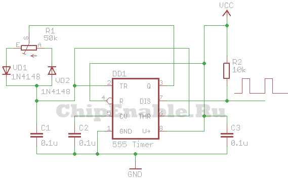
The VCC circuit supply voltage can be in the range of 5 - 16 Volts. Almost any diodes can be used as diodes VD1 - VD3.
If you are interested in understanding how this circuit works, you need to refer to the block diagram of the 555 timer. The timer consists of a voltage divider, two comparators, a flip-flop, an open collector switch and an output buffer.

The power supply (VCC) and reset pins are connected to the power supply plus, say +5 V, and the ground pin (GND) to the minus. The open collector of the transistor (DISC pin) is connected to the power supply positive through a resistor and the PWM signal is removed from it. The CONT pin is not used; a capacitor is connected to it. The THRES and TRIG comparator pins are combined and connected to an RC circuit consisting of a variable resistor, two diodes and a capacitor. The middle pin of the variable resistor is connected to the OUT pin. The extreme terminals of the resistor are connected through diodes to a capacitor, which is connected to the ground with the second terminal. Thanks to this inclusion of diodes, the capacitor is charged through one part of the variable resistor and discharged through the other.
When the power is turned on, the OUT pin is at a low logical level, then the THRES and TRIG pins, thanks to the VD2 diode, will also be at a low level. The upper comparator will switch the output to zero, and the lower one to one. The output of the trigger will be set to zero (because it has an inverter at the output), the transistor switch will close, and the OUT pin will be set to a high level (because it has an inverter at the input). Next, capacitor C3 will begin to charge through diode VD1. When it charges to a certain level, the lower comparator will switch to zero, and then the upper comparator will switch the output to one. The trigger output will be set to a unity level, the transistor switch will open, and the OUT pin will be set to a low level. Capacitor C3 will begin to discharge through diode VD2 until it is completely discharged and the comparators switch the trigger to another state. The cycle will then repeat.
The approximate frequency of the PWM signal generated by this circuit can be calculated using the following formula:
F = 1.44/(R1*C1), [Hz]
where R1 is in ohms, C1 is in farads.
With the values indicated in the diagram above, the frequency of the PWM signal will be equal to:
F = 1.44/(50000*0.0000001) = 288 Hz.
PWM DC motor speed controller
Let's combine the two circuits presented above, and we get a simple DC motor speed controller circuit, which can be used to control the engine speed of a toy, robot, micro drill, etc.
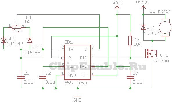
VT1 is an n-type field-effect transistor capable of withstanding the maximum motor current at a given voltage and shaft load. VCC1 is from 5 to 16 V, VCC2 is greater than or equal to VCC1.
Instead of a field-effect transistor, you can use a bipolar n-p-n transistor, a Darlington transistor, or an opto-relay of appropriate power.