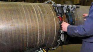
Ultrasonic inspection of welded pipe joints. Methodology for monitoring the condition of pipes and welded joints Narrow inspection of welded joints of pipelines
Monitoring the technical condition of gas pipelines is an important and responsible task. Their damage and breakthroughs can lead to man-made disasters with serious environmental consequences, financial losses and disruptions in industrial activities.
Welds at the joints of steel sections in pipelines are the most vulnerable point of the structure. Moreover, their strength does not depend on the age or novelty of the connection. They require constant monitoring of tightness.
The walls of the pipes are less vulnerable, but during operation they are subject to pressure and aggressive effects from the distilled substances from the inside and adverse external influences from the outside. As a result, even durable materials and reliable protective coatings can become damaged, deformed, deteriorate and collapse over time.
Ultrasonic testing of pipelines is used for monitoring and timely detection of defects. With its help, you can detect even the smallest or hidden imperfections in seam joints or pipe walls.
What is this technology based on?
The ultrasonic diagnostic method is based on acoustic wave vibrations, indistinguishable to human hearing, their registration and instrumental analysis. These waves travel through the metal at a certain speed. If it contains voids, the speed changes and is determined by instruments, as well as deviations in the movement of the wave flow due to encountered obstacles or places of structural heterogeneity of the material. The characteristics of acoustic waves can also be used to understand the shape and size of defects and their location.
How is ultrasonic testing of gas pipelines carried out?
When carrying out monitoring in automatic mode, infrasound systems are used that operate on the basis of hardware and software methods. Devices for collecting acoustic information, installed in groups along the pipeline at a certain distance from each other, transmit it via communication channels to control centers for integration, processing and analysis. The number, coordinates and parameters of detected flaws or leaks are recorded. The signal results are monitored by specialists on the monitor.
An automated infrasound monitoring system for pipelines allows for continuous remote verification of their operation, monitoring and control in real time with the ability to diagnose hard-to-reach areas and gas distribution compartments, using a combination of several monitoring methods simultaneously for greater accuracy of the result and prompt detection of defects and leaks. This is modern high-class equipment.
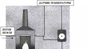
Pressure and temperature sensors, flow meters and meters of other parameters can also be connected to the system to obtain information about the technological processes occurring in the pipeline.
Advantages of the method:
- Ultrasonic inspection is a gentle and non-destructive inspection of pipelines,
- has high sensitivity and diagnostic accuracy,
- minimum time to detect leaks of gas or other substances,
- possibility of remote monitoring,
- safety,
- convenience and ease of installation and operation of the system,
- the inspection does not stop or affect the process of technical operation of the pipeline,
- suitable for all types of materials from which pipes are made,
- can be used for above-ground and underground pipe laying,
- can be carried out in any climatic conditions,
- beneficial in terms of economic costs.
Our company's proposals for pipeline monitoring.
High-quality monitoring of the condition of pipelines is a guarantee of their safe operation, reliable operation and insurance against damage. It is ensured thanks to the reliability and efficiency of the equipment used.
The SMIS Expert company develops diagnostic instruments and monitoring systems using modern scientific knowledge and innovative technologies. The use of such systems in practice ensures a high level and accuracy of monitoring the integrity of main pipelines, timely detection of any types of defects and prevention of emergency situations.
Take advantage of our services for the professional organization of ultrasonic testing of gas pipelines and other objects of increased importance when you need experience, a responsible approach and an impeccable result.
We are waiting for your applications!
Welded joints are new formations on any structure and their further safe operation largely depends on the quality of their application, and this, in turn, can only be revealed by a special check. The quality of welds of metal joints is checked using various flaw detection techniques. Of all the variety of flaw detection types that exist today, we can highlight ultrasonic testing of welded joints, which is the most accessible and inexpensive diagnostic method. Moreover, ultrasonic testing is practically not inferior in measurement accuracy to such types of non-destructive testing as fluoroscopy, gamma-scopy, radioscopy and others.
The technique of ultrasonic non-destructive testing is not a new type of flaw detection and was first put into practice in 1928, and with the development of technical progress and industrial technologies it began to be used in many areas of human activity.
The entire effect of ultrasonic testing is based on the fact that acoustic ultrasonic waves, when passing through a homogeneous medium, do not change their rectilinear trajectory of movement, but when separating media that have different structures and have different values of specific acoustic resistance, they are partially reflected. Moreover, the more significant the difference in the physical and chemical properties of materials, the greater the sound resistance at the interface between the media, the more noticeable and noticeable the effect when reflecting sound waves.
For example, when a weld is formed, a mixture of gases usually remains in the metal structure, which did not have time to escape during solidification. At the same time, the gaseous medium has actually five times less wave resistance to the passage of ultrasonic vibrations than a metal crystal lattice, which allows ultrasonic vibrations to be almost completely reflected.
Ultrasonic testing or flaw detection of welded joints is a non-destructive method for searching for internal structures that have chemical or physical deviations from specified standards, which, if unacceptable in magnitude, are defined as mechanical defects in welds.
Advantages of ultrasonic testing
Ultrasonic testing techniques are used to diagnose all types of welding, soldering and gluing, which makes it possible to identify joint defects such as:

- air voids and pores,
- delamination in the deposited weld metal,
- heat-affected cracks,
- chemically heterogeneous inclusions,
- slag deposits,
- heterogeneity of structure,
- distortion of geometric dimensions.
The main advantages of ultrasonic flaw detection include the ability to control:
- connections from both homogeneous and dissimilar materials;
- structures consisting of both metals and non-metals;
- without destruction or damage to the test samples;
- with high mobility;
- with high research speed;
- at low cost;
- without dangerous factors for personnel in comparison with X-ray or radio flaw detection.
Disadvantages of ultrasonic testing
The use of ultrasonic testing has a number of features, namely, it requires significant preparation of the test surfaces for the passage of ultrasonic waves from piezoelectric transducers through the metal structure. Necessary: 
- creation of class 5 roughness on the surface of the welded joint with the direction of the stripes perpendicular to the seam;
- applying a contact mass (in the form of water, oils) to the area under study to completely eliminate the air gap, and in the case of a vertical or strongly inclined surface, use thick pastes that are incapable of rapid drainage;
Directly the disadvantages of this flaw detection technique include:
- the need to use special piezoelectric transducers with a radius of curvature of the base in the range of +-10% of the radius of the object under study for diagnosing rounded shapes with a structure with a diameter of less than 200 mm;
- significant difficulties in studying coarse-grained structures of metals, for example, cast iron or austenite with a thickness of more than 60 mm, associated with significant attenuation and significant dispersion of ultrasonic vibrations;
- impossibility of inspecting parts with small and complex shapes;
- difficulty in assessing connections of different types of steels, which is associated with the heterogeneity of the base metals and the weld;
- the impossibility of establishing the actual sizes of various types of defects due to their shape, physical properties and location in the structure of the weld.
Types of ultrasonic inspection of seams
Ultrasonic flaw detection technology is based on the ability of high-frequency acoustic vibrations, about 20 kHz, to pass through a homogeneous structure and partially reflect from various obstacles in the form of pores, cracks and other inhomogeneities. There are several methods for obtaining the reflection of an ultrasonic signal, namely:
- shadow, which determines the difference in amplitude between transmitted and reflected vibrations;
- specular-shadow, based on determining the attenuation coefficient of reflected waves;
- echo-mirror or tandem, using two devices for its operation;
- delta method, which consists in determining the energy of vibrations reflected from a defect;
- pulse echo, which is based on the registration of reflected ultrasonic waves.
The most common are two types of flaw detection of welds using ultrasound - shadow and echo-pulse testing methods.
Methodology for ultrasonic testing
Despite the existence of several methods of ultrasonic flaw detection, their implementation is almost similar and differs only in the set of diagnostic equipment. Thus, the flaw detection procedure can be described by the following sequence:
- Careful preparation of the surface under study is carried out by mechanically removing residual slag, paint and rust from the weld seam. In addition, 50 mm strips are cleaned on both sides of it.
- The flaw detection site is generously covered with a liquid mass in the form of water, mineral oils or thick special pastes - this is necessary to allow the unhindered passage of ultrasonic waves.
- The device is pre-configured for a specific technique designed to solve specific problems.
- The ultrasonic piezoelectric transducer sequentially begins to move along a zigzag path along the weld seam.
- After receiving a stable signal, it is necessary to periodically rotate the piezoelectric transducer in different directions around its axis so as to obtain a signal with maximum image clarity on the device screen.
- When defects are detected, they are recorded and the corresponding coordinates are recorded.
- If necessary, ultrasonic testing of welds is carried out in one or several passes.
- The obtained flaw detection results are recorded in the inspection log.
GOST 17410-78
Group B69
INTERSTATE STANDARD
NON-DESTRUCTIVE TESTING
SEAMLESS CYLINDRICAL METAL PIPES
Ultrasonic flaw detection methods
Non-destructive testing. Metal seamless cylindrical pipes and tubes. Ultrasonic methods of defekt detection
ISS 19.100
23.040.10
Date of introduction 1980-01-01
INFORMATION DATA
1. DEVELOPED AND INTRODUCED by the Ministry of Heavy, Energy and Transport Engineering of the USSR
2. APPROVED AND ENTERED INTO EFFECT by Resolution of the USSR State Committee for Standards dated 06.06.78 N 1532
3. INSTEAD GOST 17410-72
4. REFERENCE REGULATIVE AND TECHNICAL DOCUMENTS
Number of paragraph, subparagraph |
|
5. The validity period was lifted according to Protocol No. 4-93 of the Interstate Council for Standardization, Metrology and Certification (IUS 4-94)
6. EDITION (September 2010) with Amendments No. 1, approved in June 1984, July 1988 (IUS 9-84, 10-88)
This standard applies to straight metal single-layer seamless cylindrical pipes made of ferrous and non-ferrous metals and alloys, and establishes methods for ultrasonic flaw detection of pipe metal continuity to identify various defects (such as violation of the continuity and homogeneity of the metal) located on the outer and inner surfaces, as well as in the thickness of the pipe walls and detected by ultrasonic flaw detection equipment.
The actual size of defects, their shape and nature are not established by this standard.
The need for ultrasonic testing, its scope and the norms of unacceptable defects should be determined in the standards or technical specifications for pipes.
1. EQUIPMENT AND REFERENCES
1.1. When testing, use: ultrasonic flaw detector; converters; standard samples, auxiliary devices and devices to ensure constant control parameters (input angle, acoustic contact, scanning step).
The standard passport form is given in Appendix 1a.
1.2. It is allowed to use equipment without auxiliary devices and devices to ensure constant control parameters when moving the converter manually.
1.3. (Deleted, Amendment No. 2).
1.4. The identified pipe metal defects are characterized by equivalent reflectivity and nominal dimensions.
1.5. The range of parameters of converters and methods of their measurements are in accordance with GOST 23702.
1.6. In the contact testing method, the working surface of the transducer is rubbed over the surface of the pipe with an outer diameter of less than 300 mm.
Instead of grinding in the transducers, it is allowed to use nozzles and supports when testing pipes of all diameters using transducers with a flat working surface.
1.7. A standard sample for adjusting the sensitivity of ultrasonic equipment during testing is a section of a defect-free pipe made of the same material, the same size and having the same surface quality as the pipe being tested, in which artificial reflectors are made.
Notes:
1. For pipes of the same range, differing in surface quality and material composition, it is allowed to manufacture uniform standard samples if, with the same equipment settings, the amplitudes of the signals from reflectors of the same geometry and the level of acoustic noise coincide with an accuracy of at least ±1.5 dB.
2. A maximum deviation of the dimensions (diameter, thickness) of standard samples from the dimensions of the controlled pipe is allowed if, with unchanged equipment settings, the amplitudes of the signals from artificial reflectors in the standard samples differ from the amplitude of the signals from artificial reflectors in standard samples of the same standard size as the controlled pipe, no more than ±1.5 dB.
3. If the metal of the pipes is not uniform in attenuation, then it is allowed to divide the pipes into groups, for each of which a standard sample of metal with maximum attenuation must be made. The method for determining attenuation must be specified in the technical documentation for control.
1.7.1. Artificial reflectors in standard samples for adjusting the sensitivity of ultrasonic equipment for monitoring longitudinal defects must correspond to Figures 1-6, for monitoring transverse defects - Figures 7-12, for monitoring defects such as delamination - Figures 13-14.
Note. It is allowed to use other types of artificial reflectors provided for in the technical documentation for control.
1.7.2. Artificial reflectors such as marks (see Fig. 1, 2, 7, 8) and rectangular groove (see Fig. 13) are used mainly for automated and mechanized control. Artificial reflectors such as a segmented reflector (see drawings 3, 4, 9, 10), notches (see drawings 5, 6, 11, 12), flat-bottomed holes (see drawing 14) are used mainly for manual control. The type of artificial reflector and its dimensions depend on the control method and the type of equipment used and must be provided for in the technical documentation for control.
Damn.1
Damn.3
Damn.8
Damn.11
1.7.3. Rectangular risks (Fig. 1, 2, 7, 8, version 1) are used to control pipes with a nominal wall thickness equal to or greater than 2 mm.
Triangular-shaped risks (Fig. 1, 2, 7, 8, version 2) are used to control pipes with a nominal wall thickness of any size.
(Changed edition, Amendment No. 1).
1.7.4. Corner reflectors of the segment type (see drawings 3, 4, 9, 10) and notches (see drawings 5, 6, 11, 12) are used for manual inspection of pipes with an outer diameter of more than 50 mm and a thickness of more than 5 mm.
1.7.5. Artificial reflectors in standard samples such as a rectangular groove (see Figure 13) and flat-bottomed holes (see Figure 14) are used to adjust the sensitivity of ultrasonic equipment to detect defects such as delaminations with a pipe wall thickness greater than 10 mm.
1.7.6. It is allowed to manufacture standard samples with several artificial reflectors, provided that their location in the standard sample prevents their mutual influence on each other when adjusting the sensitivity of the equipment.
1.7.7. It is allowed to produce composite standard samples consisting of several sections of pipes with artificial reflectors, provided that the boundaries of connecting the sections (by welding, screwing, tight fitting) do not affect the sensitivity settings of the equipment.
1.7.8. Depending on the purpose, manufacturing technology and surface quality of the pipes being monitored, one of the standard sizes of artificial reflectors, determined by the rows, should be used:
For the scratches:
Depth of notch, % of pipe wall thickness: 3, 5, 7, 10, 15 (±10%);
- length of marks, mm: 1.0; 2.0; 3.0; 5.0; 10.0; 25.0; 50.0; 100.0 (±10%);
- width of the mark, mm: no more than 1.5.
Notes:
1. The length of the mark is given for its part that has a constant depth within the tolerance; the entry and exit areas of the cutting tool are not taken into account.
2. Rounding risks associated with its manufacturing technology are allowed at the corners, no more than 10%.
For segment reflectors:
- height, mm: 0.45±0.03; 0.75±0.03; 1.0±0.03; 1.45±0.05; 1.75±0.05; 2.30±0.05; 3.15±0.10; 4.0±0.10; 5.70±0.10.
Note. The height of the segmental reflector must be greater than the length of the transverse ultrasonic wave.
For notches:
- height and width must be greater than the length of the transverse ultrasonic wave; the ratio must be greater than 0.5 and less than 4.0.
For flat bottom holes:
- diameter 2, mm: 1.1; 1.6; 2.0; 2.5; 3.0; 3.6; 4.4; 5.1; 6.2.
The distance of the flat bottom of the hole from the inner surface of the pipe should be 0.25; 0.5; 0.75, where is the pipe wall thickness.
For rectangular slots:
width, mm: 0.5; 1.0; 1.5; 2.0; 2.5; 3.0; 3.5; 4.0; 5.0; 10.0; 15.0 (±10%).
The depth should be 0.25; 0.5; 0.75, where is the pipe wall thickness.
Note. For flat-bottomed holes and rectangular grooves, other depth values are allowed, provided in the technical documentation for control.
The parameters of artificial reflectors and methods for testing them are indicated in the technical documentation for control.
(Changed edition, Amendment No. 1).
1.7.9. The height of the macro-irregularities of the surface relief of the standard sample should be 3 times less than the depth of the artificial corner reflector (marks, segmental reflector, notches) in the standard sample, according to which the sensitivity of the ultrasonic equipment is adjusted.
1.8. When inspecting pipes with a wall thickness to outer diameter ratio of 0.2 or less, artificial reflectors on the outer and inner surfaces are made of the same size.
When inspecting pipes with a large ratio of wall thickness to outer diameter, the dimensions of the artificial reflector on the inner surface should be established in the technical documentation for inspection, however, it is allowed to increase the dimensions of the artificial reflector on the inner surface of the standard sample, compared to the dimensions of the artificial reflector on the outer surface of the standard sample, without more than 2 times.
1.9. Standard samples with artificial reflectors are divided into control and working ones. Ultrasonic equipment is set up using standard working samples. Control samples are intended to test working standard samples to ensure the stability of control results.
Control standard samples are not produced if working standard samples are checked by directly measuring the parameters of artificial reflectors at least once every 3 months.
The compliance of the working sample with the control sample is checked at least once every 3 months.
Working reference materials that are not used within the specified period are checked before their use.
If the amplitude of the signal from the artificial reflector and the level of acoustic noise of the sample differs from the control by ±2 dB or more, it is replaced with a new one.
(Changed edition, Amendment No. 1).
2. PREPARATION FOR CONTROL
2.1. Before inspection, the pipes are cleaned of dust, abrasive powder, dirt, oils, paint, flaking scale and other surface contaminants. Sharp edges at the end of the pipe should not have burrs.
The need to number pipes is established depending on their purpose in the standards or technical specifications for pipes of a particular type. By agreement with the customer, pipes may not be numbered.
(Changed edition, Amendment No. 2).
2.2. Pipe surfaces must not have peeling, dents, nicks, cutting marks, leaks, splashes of molten metal, corrosion damage and must meet the surface preparation requirements specified in the technical documentation for inspection.
2.3. For mechanically processed pipes, the roughness parameter of the outer and inner surfaces according to GOST 2789 is 40 microns.
(Changed edition, Amendment No. 1).
2.4. Before testing, the compliance of the main parameters with the requirements of the technical documentation for control is checked.
The list of parameters to be checked, the methodology and frequency of their checking must be provided in the technical documentation for the ultrasonic testing equipment used.
2.5. The sensitivity of ultrasonic equipment is adjusted using working standard samples with artificial reflectors shown in Figures 1-14 in accordance with the technical documentation for control.
Setting the sensitivity of automatic ultrasonic equipment using working standard samples must meet the conditions of production inspection of pipes.
2.6. The adjustment of the sensitivity of automatic ultrasonic equipment according to a standard sample is considered complete if 100% registration of the artificial reflector occurs when the sample is passed through the installation no less than five times in a steady state. In this case, if the design of the pipe-drawing mechanism allows, the standard sample is rotated each time by 60-80° relative to the previous position before being inserted into the installation.
Note. If the mass of the standard sample is more than 20 kg, it is allowed to pass the section of the standard sample with an artificial defect five times in the forward and reverse directions.
3. CONTROL
3.1. When monitoring the quality of pipe metal continuity, the echo method, shadow or mirror-shadow methods are used.
(Changed edition, Amendment No. 1).
3.2. Ultrasonic vibrations are introduced into the pipe metal by immersion, contact or slot methods.
3.3. The applied circuits for switching on the converters during monitoring are given in Appendix 1.
It is allowed to use other schemes for switching on the converters, given in the technical documentation for control. The methods of switching on the transducers and the types of excited ultrasonic vibrations must ensure reliable detection of artificial reflectors in standard samples in accordance with paragraphs 1.7 and 1.9.
3.4. Inspection of pipe metal for the absence of defects is achieved by scanning the surface of the pipe being inspected with an ultrasonic beam.
Scanning parameters are set in the technical documentation for inspection depending on the equipment used, the inspection scheme and the size of the defects to be detected.
3.5. To increase the productivity and reliability of control, the use of multi-channel control schemes is allowed, while the transducers in the control plane must be located so as to exclude their mutual influence on the control results.
The equipment is configured according to standard samples for each control channel separately.
3.6. Checking the correctness of the equipment settings using standard samples should be carried out every time the equipment is turned on and at least every 4 hours of continuous operation of the equipment.
The frequency of inspection is determined by the type of equipment used, the control circuit used and should be established in the technical documentation for control. If a setting violation is detected between two inspections, the entire batch of inspected pipes is subject to re-inspection.
It is allowed to periodically check the equipment settings during one shift (no more than 8 hours) using devices whose parameters are determined after setting up the equipment according to a standard sample.
3.7. The method, basic parameters, circuits for switching on the transducers, the method of introducing ultrasonic vibrations, the sounding circuit, methods for separating false signals and signals from defects are established in the technical documentation for control.
The form of the ultrasonic pipe inspection card is given in Appendix 2.
3.6; 3.7. (Changed edition, Amendment No. 1).
3.8. Depending on the material, purpose and manufacturing technology, pipes are checked for:
a) longitudinal defects during the propagation of ultrasonic vibrations in the pipe wall in one direction (adjustment using artificial reflectors, Fig. 1-6);
b) longitudinal defects when ultrasonic vibrations propagate in two directions towards each other (adjustment using artificial reflectors, Fig. 1-6);
c) longitudinal defects when ultrasonic vibrations propagate in two directions (tuning using artificial reflectors, Fig. 1-6) and transverse defects when ultrasonic vibrations propagate in one direction (tuning using artificial reflectors, Fig. 7-12);
d) longitudinal and transverse defects during the propagation of ultrasonic vibrations in two directions (adjustment using artificial reflectors Fig. 1-12);
e) defects such as delaminations (adjustment using artificial reflectors (Fig. 13, 14) in combination with subparagraphs a B C D.
3.9. When monitoring, the sensitivity of the equipment is adjusted so that the amplitudes of the echo signals from the external and internal artificial reflectors differ by no more than 3 dB. If this difference cannot be compensated for by electronic devices or methodological techniques, then inspection of pipes for internal and external defects is carried out through separate electronic channels.
4. PROCESSING AND REGISTRATION OF CONTROL RESULTS
4.1. The continuity of pipe metal is assessed based on the results of analysis of information obtained as a result of control, in accordance with the requirements established in the standards or technical specifications for pipes.
Information processing can be performed either automatically using appropriate devices included in the control installation, or by a flaw detector based on visual observations and measured characteristics of detected defects.
4.2. The main measured characteristic of defects, according to which pipes are sorted, is the amplitude of the echo signal from the defect, which is measured by comparison with the amplitude of the echo signal from an artificial reflector in a standard sample.
Additional measured characteristics used in assessing the quality of pipe metal continuity, depending on the equipment used, the design and method of control and artificial tuning reflectors, and the purpose of the pipes are indicated in the technical documentation for control.
4.3. The results of ultrasonic testing of pipes are entered into the registration log or in the conclusion, where the following should be indicated:
- pipe size and material;
- scope of control;
- technical documentation based on which control is performed;
- control circuit;
- an artificial reflector, which was used to adjust the sensitivity of the equipment during testing;
- numbers of standard samples used when setting up;
- type of equipment;
- nominal frequency of ultrasonic vibrations;
- converter type;
- scanning parameters.
Additional information to be recorded, the procedure for preparing and storing the journal (or conclusion), and methods for recording identified defects must be established in the technical documentation for control.
The form of the ultrasonic pipe inspection log is given in Appendix 3.
(Changed edition, Amendment No. 1).
4.4. All repaired pipes must undergo repeated ultrasonic testing to the full extent specified in the technical documentation for testing.
4.5. Entries in the journal (or conclusion) serve for constant monitoring of compliance with all requirements of the standard and technical documentation for inspection, as well as for statistical analysis of the effectiveness of pipe inspection and the state of the technological process of their production.
5. SAFETY REQUIREMENTS
5.1. When carrying out work on ultrasonic testing of pipes, the flaw detector must be guided by the current “Rules for the technical operation of consumer electrical installations and technical safety rules for the operation of consumer electrical installations”*, approved by Gosenergonadzor on April 12, 1969 with additions dated December 16, 1971 and agreed upon with the All-Russian Central Council of Trade Unions on April 9, 1969.
________________
* The document is not valid on the territory of the Russian Federation. The Rules for the Technical Operation of Consumer Electrical Installations and the Interindustry Rules for Labor Protection (Safety Rules) for the Operation of Electrical Installations are in force (POT R M-016-2001, RD 153-34.0-03.150-00). - Database manufacturer's note.
5.2. Additional requirements for safety and fire safety equipment are established in the technical documentation for control.
When using the echo control method, combined (Fig. 1-3) or separate (Fig. 4-9) circuits for switching on the converters are used.
When combining the echo method and the mirror-shadow control method, a separate-combined circuit for switching on the transducers is used (Fig. 10-12).
With the shadow control method, a separate (Fig. 13) circuit for switching on the converters is used.
With the mirror-shadow control method, a separate (Fig. 14-16) circuit for switching on the converters is used.
Note to drawings 1-16: G- output to the ultrasonic vibration generator; P- output to the receiver.
Damn.4
Damn.6
Damn.16
APPENDIX 1. (Changed edition, Amendment No. 1)
APPENDIX 1a (for reference). Passport for a standard sample
APPENDIX 1a
Information
PASSPORT
per standard sample N
Manufacturer's name | ||||||||||
Date of manufacture | ||||||||||
Purpose of a standard sample (working or control) | ||||||||||
Material grade | ||||||||||
Pipe size (diameter, wall thickness) | ||||||||||
Type of artificial reflector according to GOST 17410-78 | ||||||||||
Type of reflector orientation (longitudinal or transverse) | ||||||||||
Dimensions of artificial reflectors and measurement method:
Reflector type | Application surface | Measuring method | Reflector parameters, mm |
|||
Risk (triangular or rectangular) | ||||||
Segmental reflector | ||||||
Flat bottom hole | distance |
|||||
Rectangular groove | ||||||
Date of periodic inspection | |||||||||
job title | surname, i., o. | ||||||||
Notes:
1. The passport indicates the dimensions of artificial reflectors that are manufactured in this standard sample.
2. The passport is signed by the heads of the service conducting certification of reference materials and the technical control department service.
3. In the column “Measurement method” the measurement method is indicated: direct, using casts (plastic impressions), using witness samples (amplitude method) and the instrument or device used to carry out the measurements.
4. In the column “Application surface” the internal or external surface of the standard sample is indicated.
APPENDIX 1a. (Introduced additionally, Amendment No. 1).
APPENDIX 2 (recommended). Map of ultrasonic inspection of pipes using manual scanning method
Number of technical documentation for control | ||||||||||||
Pipe size (diameter, wall thickness) | ||||||||||||
Material grade | ||||||||||||
Number of technical documentation regulating suitability assessment standards | ||||||||||||
Volume of control (direction of sound) | ||||||||||||
Converter type | ||||||||||||
Converter frequency | ||||||||||||
Beam angle | ||||||||||||
Artificial reflector type and size (or reference number) for adjusting fixation sensitivity | ||||||||||||
and search sensitivity | ||||||||||||
Type of flaw detector | ||||||||||||
Scan parameters (step, control speed) | ||||||||||||
Note. The map must be drawn up by engineering and technical workers of the flaw detection service and agreed, if necessary, with the interested services of the enterprise (department of the chief metallurgist, department of the chief mechanic, etc.).
Date of con- | Number of package, presentation, certificate | If- | Control parameters (standard sample number, size of artificial defects, type of installation, control circuit, operating frequency of ultrasonic testing, converter size, control step) | Numbers checked | Ultrasound testing results | Signature defective |
|||
Once- | Mate- | pipe numbers without details | numbers of pipes with defects | ||||||
APPENDIX 3. (Changed edition, Amendment No. 1).
Electronic document text
prepared by Kodeks JSC and verified against:
official publication
Metal and connecting pipes
parts for them. Part 4. Black pipes
metals and alloys cast and
connecting parts to them.
Basic dimensions. Technological methods
pipe testing: Sat. GOST. -
M.: Standartinform, 2010
Seams in structures with welded joints must be constantly monitored. And this does not depend on when the connection was made. For this, various methods are used, one of which is ultrasonic flaw detection (USD). In terms of the accuracy of the studies performed, it surpasses fluoroscopy, radio flaw detection, and gamma flaw detection.
It should be noted that this technique is not new. It has been used since the thirties of the last century, and today ultrasonic testing of welded joints is popular because it can help identify the smallest defects inside the weld. And, as practice shows, it is hidden defects that are the main serious reasons for the unreliability of the welded structure.
 Ultrasonic flaw detection technology. (On the left there is no defect, on the right there is a defect)
Ultrasonic vibrations are based on ordinary acoustic waves, which have a vibration frequency above 20 kHz. The person does not hear them. Penetrating into the metal, the waves fall between its particles, which are in equilibrium, that is, they oscillate in the same phase. The distance between them is equal to the ultrasonic wavelength. This indicator depends on the speed of passage through the metal seam and the frequency of the vibrations themselves. The dependence is determined by the formula:
- L is the wavelength;
- c is the speed of its movement;
- f – oscillation frequency.
The speed depends on the density of the material. For example, ultrasonic waves move faster in the longitudinal direction than in the transverse direction. That is, if there are voids (another medium) in the path of the wave, then its speed also changes. At the same time, encountering various defects along the way, waves are reflected from the walls of shells, cracks and voids. And, accordingly, deviation from the directional flow. The operator sees the change in movement on the monitor of the ultrasonic instrument and, based on certain characteristics, determines which defect stands in the way of the movement of acoustic waves.
For example, attention is paid to the amplitude of the reflected wave, thereby determining the size of the defect in the weld. Or by the time of propagation of an ultrasonic wave in the metal, which determines the distance to the defect.
Types of ultrasonic testing
Currently, several methods of ultrasonic flaw detection of welds are used in industry. Let's look at each of them.
- Shadow diagnostic method. This technique is based on the use of two transducers at once, which are installed on opposite sides of the object under study. One of them is an emitter, the second is a receiver. The installation location is strictly perpendicular to the plane of the weld being examined. The emitter directs a stream of ultrasonic waves to the seam, and the receiver receives them from the other side. If a blind zone is formed in the flow of waves, this indicates that a section with a different medium has come across its path, that is, a defect is detected.
- Pulse echo method. For this, one ultrasonic flaw detector is used, which both emits waves and receives them. In this case, the technology of ultrasound reflection from the walls of defective areas is used. If the waves passed through the metal of the weld and were not reflected on the receiving device, then there are no defects in it. If there is a reflection, it means there is some kind of flaw inside the seam.
- Echo-mirror. This ultrasonic testing of welds is a subtype of the previous one. It uses two devices: an emitter and a receiver. They are only installed on one side of the metal being tested. The emitter sends waves at an angle, they hit defects and are reflected. These reflected vibrations are received by the receiver. Usually, in this way, vertical defects inside the weld seam are recorded - cracks.
- Mirror-shadow. This ultrasonic testing method is a symbiosis of shadow and mirror. Both devices are installed on one side of the metal being tested. The emitter sends oblique waves, they are reflected from the wall of the base metal and received by the receiver. If no flaws in the weld seam are encountered on the path of the reflected waves, then they pass without changes. If a blind zone is reflected on the receiver, then it means there is a flaw inside the seam.
- Delta method. This method of ultrasonic testing of welded joints is based on the re-emission of directed acoustic vibrations by a defect into the welded joint. In fact, reflected waves are divided into mirror waves, transformed in the longitudinal direction and re-emitted. The receiver may not pick up all the waves, mostly reflected and moving directly towards it. The size of the defect and its shape will depend on the number of waves received. Not the best test, because it involves fine-tuning the equipment, and it is difficult to decipher the results obtained, especially when a welding seam more than 15 mm wide is checked. When carrying out ultrasonic quality control of metal using this method, strict requirements are imposed on the cleanliness of the weld seam.
These are the ultrasonic testing methods used today to determine the quality of welded joints. It should be noted that most often specialists use pulse-echo and shadow methods. The rest are less common. Both options are mainly used in ultrasonic inspection of pipes.
How is ultrasonic flaw detection performed?
All of the technologies described above belong to the category of ultrasonic non-destructive testing methods. They are convenient and easy to use. Let's look at how the shadow method is used in practice. All actions are carried out in accordance with GOST.
- The weld seam and adjacent areas are cleaned to a width of 50-70 mm on each side.
- To obtain more accurate results, a lubricant is applied to the connecting seam. For example, it could be solid oil, glycerin or any other technical oil.
- The device is configured according to GOST.
- The emitter is installed on one side and turned on.
- On the opposite side, the finder (receiver) makes zigzag movements along the welded joint. In this case, the device is slightly rotated back and forth around its axis by 10-15°.
- As soon as a signal with maximum amplitude appears on the monitor, it is likely that a defect has been detected in the weld metal. But you need to make sure that the reflective signal does not cause unevenness in the seam.
- If not confirmed, then the coordinates of the flaw are recorded.
- According to GOST, the test is carried out in two or three passes.
- All results are recorded in a special journal.
Attention! Quality control of welded corner joints (T-joints) is carried out only by the echo-pulse method; the shadow method is not suitable here.
Results Evaluation Options
The sensitivity of the device is the main factor in the quality of the work performed. How can you use it to recognize the parameters of a defect?
First, the number of flaws is determined. Even at the closest distances to each other, the echo method can determine: one defect in the weld or two (several). They are assessed according to the following criteria:
- acoustic wave amplitude;
- its length (conditional);
- size of the defect and its shape.
The length of the wave and the width of the flaw can be determined by moving the emitter along the weld joint. The height of a crack or hole can be determined based on the difference in time intervals between the reflected wave and the previously emitted one. The shape of the defect is determined by a special technique. It is based on the shape of the reflected signal appearing on the monitor.
The ultrasonic flaw detection method is complex, so the quality of the results obtained depends on the qualifications of the operator and the compliance of the obtained indicators, which are regulated by GOST.
Advantages and disadvantages of ultrasonic pipe inspection
The advantages of the method for monitoring welds include the following criteria.
- The examination goes quickly.
- The diagnostic result is high.
- The ultrasonic weld inspection method is the cheapest option.
- It is also the safest for humans.
- The device for seam quality control is a portable device, so the mobility of the technology is ensured.
- Ultrasonic diagnostics are carried out without damaging the part being examined.
- There is no need to stop the equipment or site in order to carry out welding inspection.
- You can check the joints of stainless metals, ferrous and non-ferrous.
There are also disadvantages.
- Inspection of welded joints of pipelines or other structures does not provide accuracy in the shape of the defect found. The thing is that air (gas) or slag may be present in the cracks or cavities of the weld. The two materials have different densities and therefore different reflectivities.
- It is difficult to identify defects in parts with complex configurations. The sent waves can be reflected on another section of the seam, and not on the one under study, due to curvature. And this will give incorrect information.
- It is difficult to carry out ultrasonic testing of pipes if the metal from which they are made has a coarse-grained structure. Inside the material, the directional flow will be dissipated and the reflected waves will be attenuated.
- It is important to take a responsible approach to cleaning the weld. Its waviness or contamination, rust or scale, drops of splashed metal or air seats and pores on the surface will create an obstacle to obtaining the correct indicators that comply with GOST.
In the construction industry, pipes with a diameter of 28 to 1420 mm and a wall thickness of 3 to 30 mm are used. Based on flaw detection, the entire range of pipe diameters can be divided into three groups:
- 28...100 mm and H = 3...7 mm
- 108...920 mm and H= 4...25 mm
- 1020...1420 mm and H= 12...30 mm
Conducted by specialists from MSTU. N.E. Bauman's research shows that it is necessary to take into account the anisotropy of the elastic properties of the material when developing methods for ultrasonic testing of welded pipe joints.
Features of anisotropy of pipe steel.
It is assumed that the speed of propagation of transverse waves does not depend on the direction of sounding and is constant over the cross section of the pipe wall. But ultrasonic testing of welded joints of main gas pipelines made from foreign and Russian pipes revealed a significant level of acoustic noise, the omission of large root defects, as well as incorrect assessment of their coordinates.
It has been established that, subject to optimal control parameters and compliance with the testing procedure, the main reason for missing a defect is the presence of a noticeable anisotropy in the elastic properties of the base material, which affects the speed, attenuation, and deviation from straightness of the ultrasonic beam propagation.
Having sounded the metal of more than 200 pipes according to the scheme shown in Fig. 1, it was revealed that the standard deviation of the wave speed for a given direction of propagation and polarization is 2 m/s (for transverse waves). Deviations of speeds from the table ones by 100 m/s or more are not accidental and are most likely associated with the production technology of rolled products and pipes. Deviations on such scales significantly affect the propagation of polarized waves. In addition to the described anisotropy, inhomogeneity of the speed of sound across the thickness of the pipe wall was revealed.
Rice. 1. Designations of deposits in the pipe metal: X, Y, Z. - directions of ultrasound propagation: x. y.z: - polarization directions; Y - rolling direction: Z - perpendicular to the plane of the pipe
Rolled sheets have a layered texture, consisting of fibers of metal and non-metallic inclusions, elongated during deformation. Sheet zones of unequal thickness are subject to various deformations as a result of the influence of the thermomechanical rolling cycle on the metal. This leads to the fact that the speed of sound is additionally affected by the depth of the sounding layer.
Inspection of welded seams of pipes of various diameters.
Pipes with a diameter of 28...100 mm.
Welded seams in pipes with a diameter of 28 to 100 mm and a height of 3 to 7 mm have such a feature as the formation of sagging inside the pipe, this, when inspected with a direct beam, leads to the appearance of false echo signals on the screen of the flaw detector, which coincide in time with the echo signals, reflected from root defects, which are detected by a single reflected beam. Since the effective width of the beam is commensurate with the thickness of the pipe wall, the reflector usually cannot be found by the location of the finder relative to the reinforcement roller. There is also an uncontrolled zone in the center of the seam due to the large width of the seam bead. All this leads to the fact that the probability of detecting unacceptable volumetric defects is low (10-12%), but unacceptable planar defects are determined much more reliably (~ 85%). The main parameters of sagging (width, depth and angle of contact with the surface of the product) are considered random variables for a given pipe size; the average parameter values are 6.5 mm; 2.7 mm and 56°30" respectively.
Rolled steel behaves as an inhomogeneous and anisotropic medium with rather complex dependences of the velocities of elastic waves on the direction of sounding and polarization. The change in sound speed is closely symmetrical relative to the middle of the sheet section, and near this middle the transverse wave speed can decrease significantly (up to 10%) relative to the surrounding areas. The shear wave speed in the objects under study varies in the range of 3070...3420 m/s. At a depth of up to 3 mm from the surface of the rolled product, a slight (up to 1%) increase in the shear wave speed is likely.
The noise immunity of control is significantly enhanced when using inclined separate-combined probes of the RSN type (Fig. 2), called chord probes. They were created at MSTU. N.E. Bauman. The peculiarity of the inspection is that when identifying defects, transverse scanning is not necessary; it is only needed along the perimeter of the pipe when the front face of the transducer is pressed against the seam.
Rice. 2. Inclined chord RSN-PEP: 1 - emitter: 2 - receiver
Pipes with a diameter of 108...920 mm.
Pipes with a diameter of 108-920 mm and with H in the range of 4-25 mm are also performed by one-sided welding without back welding. Until recently, control over these connections was controlled by combined probes according to the methodology outlined for pipes with a diameter of 28-100 mm. But the known control technique assumes the presence of a significantly large zone of coincidence (zone of uncertainty). This leads to insignificant reliability of assessing the quality of the connection. Combined probes have a high level of reverberation noise, which complicates the decoding of signals, and uneven sensitivity, which cannot always be compensated for by available means. The use of chordal separate-combined probes for monitoring a given standard size of welded joints is not effective due to the fact that due to the limited values of the input angles of ultrasonic vibrations from the surface of the welded joint, the dimensions of the transducers increase disproportionately, and the area of acoustic contact increases.
Created at MSTU. N.E. Bauman inclined probes with equalized sensitivity are used to control welded joints with a diameter of more than 10 cm. Equalization of sensitivity is achieved by choosing a rotation angle of 2 so that the middle and upper part of the weld is sounded by a central, single-reflected beam, and the lower part is examined by direct peripheral rays incident on the defect at an angle Y, from central. In Fig. 3. shows a graph of the dependence of the angle of input of the transverse wave on the angle of rotation and opening of the directional pattern Y. Here in the probe, the waves incident and reflected from the defect are horizontally polarized (SH-wave).
Rice. 3. Changing the input angle alpha, within the limit of half the opening angle of the RSN-PEP radiation pattern, depending on the rotation angle delta.
The graph shows that when testing products H = 25 mm, the uneven sensitivity of the RS-probe can be up to 5 dB, and for a combined probe it can reach 25 dB. RS-PEP has an increased signal level and has increased absolute sensitivity. The RS-PEP clearly reveals a notch with an area of 0.5 mm2 when inspecting a welded joint 1 cm thick with both a direct and a single reflected beam at a useful signal/interference ratio of 10 dB. The process of monitoring the considered probes is similar to the procedure for conducting combined probes.
Pipes with a diameter of 1020...1420 mm.
To make welded joints of pipes with a diameter of 1020 and 1420 mm with H in the range from 12 to 30 mm, double-sided welding or welding with back welding of the seam bead is used. In seams made by double-sided welding, false signals from the trailing edge of the reinforcement bead most often have less interference than in single-sided welds. They are smaller in amplitude due to the smoother contours of the roller further along the sweep. In this regard, this is the most convenient pipe size for flaw detection. But conducted at MSTU. N.E. Bauman's research shows that the metal of these pipes is characterized by the greatest anisotropy. In order to minimize the effect of anisotropy on the detection of defects, it is best to use a probe at a frequency of 2.5 MHz with a prism angle of 45°, and not 50°, as advised in most regulatory documents for testing such connections. Higher control reliability was achieved when using RSM-N12 type probes. But unlike the method outlined for pipes with a diameter of 28-100 mm, there is no zone of uncertainty when monitoring these connections. Otherwise, the control principle remains the same. When using the RS-PEP, it is recommended to adjust the scan speed and sensitivity according to vertical drilling. The scanning speed and sensitivity of inclined combined probes should be adjusted using corner reflectors of the appropriate size.
When inspecting welds, it is necessary to remember that metal delamination may occur in the heat-affected zone, which complicates the determination of the coordinates of the defect. The area with a defect found by an inclined probe must be checked with a direct probe to clarify the characteristics of the defect and identify the true value of the depth of the defect.
In the petrochemical industry and nuclear energy, clad steels are widely used for the production of pipelines and vessels. Austenitic steels applied by surfacing, rolling or explosion with a thickness of 5-15 mm are used as cladding for the inner wall of such structures.
The method of monitoring these welded joints involves assessing the continuity of the pearlite part of the weld, including the fusion zone with restorative anti-corrosion surfacing. The continuity of the surfacing body itself is not subject to control.
But due to the difference in the acoustic properties of the base metal and austenitic steel from the interface during ultrasonic testing, echo signals appear that interfere with the detection of defects such as cladding delaminations and sub-cladding cracks. The presence of cladding significantly affects the parameters of the acoustic path of the probe.
In this regard, standard technological solutions for monitoring thick-walled welds of clad pipelines do not give the desired result.
Long-term research by a number of specialists: V.N. Radko, N.P. Razygraeva, V.E. Bely, V.S. Grebennik and others made it possible to determine the main features of the acoustic path, develop recommendations for optimizing its parameters, and create a technology for ultrasonic testing of welds with austenitic cladding.
In the works of specialists, it was established that when a beam of ultrasonic waves is re-reflected from the pearlite-austenitic cladding boundary, the directional pattern almost does not change in the case of rolling cladding and is significantly deformed in the case of surfacing cladding. Its width increases sharply, and within the main lobe oscillations of 15-20 dB appear, depending on the type of surfacing. There is a significant displacement of the reflection exit point from the beam cladding boundary compared to its geometric coordinates and a change in the speed of transverse waves in the transition zone.
Taking these features into account, the technology for monitoring welded joints of clad pipelines requires preliminary mandatory measurement of the thickness of the pearlite part.
Better detection of planar defects (cracks and lack of fusion) is achieved by using a probe with an input angle of 45° and a frequency of 4 MHz. The better detection of vertically oriented defects at an input angle of 45° compared to angles of 60 and 70° is due to the fact that when the latter are sounded, the angle at which the beam meets the defect is close to the 3rd critical angle, at which the shear wave reflection coefficient is the smallest.
At a frequency of 2 MHz, when sounded outside the pipe, echoes from defects are shielded by an intense and long-lasting noise signal. The noise immunity of the probe at a frequency of 4 MHz is on average 12 dB higher, which means the useful signal from a defect located in the immediate vicinity of the surfacing boundary will be better resolved against the background noise.
When sounding from inside the pipe through the surfacing, maximum noise immunity is established when the probe is set to a frequency of 2 MHz.
The method of monitoring pipeline welds with surfacing is regulated by the Gosatomnadzor guidelines document RFPNAEG-7-030-91.