Vertical drilling. How to connect a single-phase motor Diagram with two capacitors
Single-phase motors are low-power electrical machines. The magnetic circuit of single-phase motors contains a two-phase winding, consisting of a main winding and a starting winding.
Two windings are needed to cause the rotor of a single-phase motor to rotate. The most common motors of this type can be divided into two groups: single-phase motors with a starting winding and motors with a running capacitor.
For engines of the first type, the starting winding is switched on through a capacitor only at the time of start-up and after the engine has developed a normal rotation speed, it is disconnected from the network. The motor continues to operate with one working winding. The size of the capacitor is usually indicated on the motor nameplate and depends on its design.
For single-phase asynchronous AC motors with a running capacitor, the auxiliary winding is permanently connected through a capacitor. The value of the working capacitance of the capacitor is determined by the design of the engine.
That is, if the auxiliary winding of a single-phase motor is starting, its connection will occur only during the start-up, and if the auxiliary winding is a capacitor, then its connection will occur through a capacitor, which remains turned on during engine operation.
It is necessary to know the design of the starting and operating windings of a single-phase motor. The starting and operating windings of single-phase motors differ in both the cross-section of the wire and the number of turns. The working winding of a single-phase motor always has a larger wire cross-section, and therefore its resistance will be less.
Look at the photo and you can clearly see that the wire cross-sections are different. The winding with a smaller cross-section is the starting one. You can measure the resistance of the windings using dial and digital testers, as well as an ohmmeter. The winding with less resistance is working.
Rice. 1. Working and starting windings of a single-phase motor
Now here are a few examples you may encounter:
If the motor has 4 terminals, then having found the ends of the windings and after measuring, you can now easily figure out these four wires, less resistance is the working one, more resistance is the starting one. Everything is connected simply, 220V is supplied to the thick wires. And one end of the starting winding, for one of the workers. On which of them there is no difference, the direction of rotation does not depend on it. It also depends on how you insert the plug into the socket. The rotation will change depending on the connection of the starting winding, namely, by changing the ends of the starting winding.
Next example. This is when the motor has 3 terminals. Here the measurements will look like this, for example - 10 ohms, 25 ohms, 15 ohms. After several measurements, find the tip from which the readings, with two others, will be 15 ohms and 10 ohms. This will be one of the network wires. The tip that shows 10 ohms is also the network one and the third 15 ohm will be the starting one, which is connected to the second network one through a capacitor. In this example, the direction of rotation, you will not change what it is and will be. Here, in order to change the rotation, you will need to get to the winding diagram.
Another example when measurements can show 10 ohms, 10 ohms, 20 ohms. This is also one of the types of windings. These came on some models of washing machines, and not only that. In these motors, the working and starting windings are the same (according to the design of three-phase windings). It makes no difference what kind of working winding you have and what kind of starting winding. , is also carried out through a capacitor.
Edited by A. Povny
To make two-wire lines, you need to take brass or copper wire with a diameter of 1.5-4-2 mm. The narrow line is filled with node G (Fig. 5), which is designed as follows. A matching device made of tubes with a diameter of 10 mm is connected to the narrow line. At one end, the tubes of the matching device are closed together with metal strips and mounted on the wall or roof of the house near the input of the cable going to the TV (the ends need to be fixed at such a height that the antenna can be easily adjusted, but at the same time the line cannot be accidentally damaged ).
The cable going to the TV (preferably RKZ type) is connected to the matching device through a balun. The role of the conductors of the balun is performed by the shielding braids of the RK-3 cable sections, the ends of which are short-circuited on one side and connected to the tubes of the matching device on the other. The location of this connection should be determined experimentally using the successive approximation method. This can be done this way: by first installing
size L2=--p, where Jasr is average
the wavelength of the television channel whose reception is intended, the best image reception is achieved by first changing the size Lx by moving the clamps of the balun along the tubes of the matching device, and then changing the size L2 by moving the short-circuiting strips along the shielding braid of the cables of the balun. This operation should be done two to three times. Having chosen the best one from various setting options, the clamps and strips are tightly secured, and the exposed parts of the RK-3 cable are insulated to protect them from moisture. To tune the antenna, you can also change the length of the matching device by moving the bars that short-circuit the tubes of this device.
The described antenna system is quite bulky, and therefore care must be taken to ensure its rigidity. In Fig. 7, o and 7, b show one of the options for securing the system. Guys give the device the necessary stability. Some of
them (shown in the figures) need to be separated by insulators, placing the latter relative to each other
at a distance smaller than
(Yamin is the minimum wavelength of the operating range of the antenna). Attention should be paid to strengthening node B with a guy rope, preventing excessive sagging of wide supply lines and freeing them from mechanical loads. The guy rope must be attached to the lines in node B through an insulation board without disturbing the symmetry of the power system.
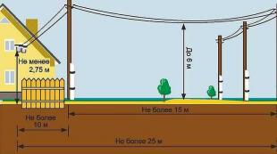
The height of the mast on which the antenna system is located should be selected so that the center of the system is higher than objects (buildings, trees, etc.) located in the direction of the television center for 1.5-2 km. The width of the main lobe of the antenna system's radiation pattern at half power level is approximately 25°. This circumstance places increased demands on the alignment of the antenna in a given direction. It is undesirable for the maximum deviations from the direction of the telecentre to exceed ±.5°.
ELECTRIC MOTORS PLANT "ELFA"
Electric motors produced by the Vilnius Elfa plant are widely used in many household electrical appliances and tape recorders. counting and writing machines. Over the past year, the plant has been working on the production of more than twenty types of asynchronous electric motors for various purposes.
In Fig. 1 shows dimensional drawings of the most common asynchronous single-phase low-power electric motors of the K.D, DAO, DKhM, KDR and DKS types. The main parameters of these electric motors are shown in table. 1, and their overall dimensions are in table. 2.
An electric motor with a squirrel-cage rotor and a DAO-type starting winding (Fig. 1.6) is designed to drive household washing machines and other electrical appliances. The electric motor connection diagram is shown in Fig. 2.
Electric motors of types DXM-3 and DXM-5 (Fig. 1, c) - asynchronous, single-phase, with short-circuited rotor
torus and starting winding of built-in design. They are designed to drive the compressor of domestic electric home refrigerators. The connection circuit for a DXM type motor is similar to the connection circuit for an electric motor of the DAO type (rns. 2).
Electric motor type KD-2 (Fig. 1, o) is an asynchronous single-phase with a squirrel-cage rotor, capacitor, used to drive the tape drive mechanism of a tape recorder. The engine switching diagram is shown in Fig. 3.
The electric motor '™ na KD-P (Fig. 1, a) is an asynchronous single-phase, capacitor. The rotor of this motor is made with an open squirrel cage, which allows for a soft characteristic. The engine is designed to drive the tape drive mechanism of sound recording equipment for winding and rewinding magnetic tape. The engine switching diagram is shown in Fig. 4.
Electric motor KD-30 (Fig. 1, a) - asynchronous, single-phase, capacitor, short-circuited
L. Tsyganova
rotor, designed to drive cash registers of the KI and KO types. The motor connection diagram is shown in Fig. 5.
The electric motor KD-3.5 (Fig. 1, o) is an asynchronous, single-phase, capacitor, with a squirrel-cage rotor, designed for operation in sound recording equipment at ambient temperatures from 5 to 75 ° C. The engine switching diagram is shown on the RNS. 6.
The electric motor KD-25 (Fig. 1, o) is an asynchronous, single-phase, capacitor, with a squirrel-cage rotor, designed to drive a band puncher and an EP electrofiled typewriter. The engine switching diagram is shown in Fig. 7.
Electric motor KD-50 (Fig. 1, c) is an asynchronous single-phase, capacitor, with a squirrel-cage rotor, can be used to drive an oscilloscope of type N102 and N105. The engine switching diagram is shown in Fig. 8.
Electric motor KD-50S (Fig.!, a) - asynchronous, single-phase,
As a 3-year-old boy, I bought myself for 113 rubles. Motorcycle MV-18. In my opinion, this is the most successful version of a bicycle moped. I drove it for 17 years and my son already broke it. 3 years ago I saw on the market a Chinese Hole Forester with an F50 (KD50) bicycle motor. I remembered my childhood and bought it for 11,300 rubles. I would like to give a comparative analysis of the D and KD motors. It makes sense to compare D8 and KD50: D8 is the last in the D series, KD50 and KD80 are structurally identical. Both models have a common ancestor D5. There is a version that the USSR transferred the D4 and D5 production lines to the PRC. What is the difference between D8 and KD50 from D5. More advanced power supply, ignition and exhaust systems. The D8 carburetor is more convenient to adjust. On my D6, I adjusted the mixture quality on the go on almost every trip. The ignition system now has a light winding and an ignition coil. The new muffler gave a significant increase in power. In short, modernization proceeded by complicating the design. The Chinese took a different route. The carburetor has become simpler. Adjusting the quality of the mixture is achieved by setting the fuel level in the float chamber. The air filter mesh set has been replaced with foam rubber. The spool fuel supply system has been replaced by a piston one. The ignition on the CD has become electronic. Moreover, my Forester has a UOZ centrifugal regulator. Sometimes there is a light winding present. The CD clutch has become single-plate. Manipulating the muffler allows you to increase engine power. The Chinese abandoned the cast iron cylinder liner. In general, the D8 engine is more durable than the KD50. But more often it requires maintenance. CD is more powerful and simpler. Spare parts are quite available for both. The most common malfunction of my D6: The engine does not start - there is a spark, the spark plug is wet. As a kid, in such cases, I cut circles around the block, periodically changing the position of the air filter flap. My MV-18 lived for 17 years because I acted on the principle of “do no harm.” Until a diagnosis has been established, there is no need to tighten the screws. You always have to think, can you return everything to the way it was? The best is the enemy of the good. If your hands are still itching, then first buy the part that you want to modernize and experiment with it. Now some advice for beginners. A bicycle moped is a low-budget option. The following tips. If Grandpa's Dashka is lying around somewhere, try to revive it. You can find spare parts on the Internet. If you have the opportunity to buy a ready-made bicycle moped, take it. If you are going to install a velomotor on a bicycle, first buy a velomotor (KD50 is faster, KD80 is faster, you can find a new D8, but I don’t recommend it). Criteria for choosing a bike: I strongly recommend front shock absorbers (otherwise you will hit the 5th point and the spokes will fly). If it’s expensive, then don’t buy it with small wheels (for the same reason): where the big wheel rolls over an obstacle, the small one hits. Now regarding the operation. If you browse moped forums, you will find a lot of smart tuning tips. If a bicycle moped is your means of transportation, then ride until something breaks. The main criterion for engine tuning is the color of the spark plug electrodes (brick). The developers of the D series recommended a new type of spark plug for each model, from A10 on D4 to A23 on D8. So try it yourself. KD has something Chinese in it. A plug that is too hot results in hot ignition; a plug that is too cold causes oiling. Now about the ignition. Electronic ignition is more reliable and does not require maintenance. But if you have a contact ignition, then do not try to throw it away. The OZ can be changed on it as well. Parts are available for sale. The D5 had one magneto and cams. They suggest replacing the cams with a board and a bobbin. The ignition is faulty - what should I change? If you are comfortable with electronics, take the flag into your hands. If not, buy a CD ignition and, after tinkering a little, set it to D.
To make two-wire lines, you need to take brass or copper wire with a diameter of 1.5-4-2 mm. The narrow line is filled with node G (Fig. 5), which is designed as follows. A matching device made of tubes with a diameter of 10 mm is connected to the narrow line. At one end, the tubes of the matching device are closed together with metal strips and mounted on the wall or roof of the house near the input of the cable going to the TV (the ends need to be fixed at such a height that the antenna can be easily adjusted, but at the same time the line cannot be accidentally damaged ).
The cable going to the TV (preferably RKZ type) is connected to the matching device through a balun. The role of the conductors of the balun is performed by the shielding braids of the RK-3 cable sections, the ends of which are short-circuited on one side and connected to the tubes of the matching device on the other. The location of this connection should be determined experimentally using the successive approximation method. This can be done this way: by first installing
size L2=--p, where Jasr is average
the wavelength of the television channel whose reception is intended, the best image reception is achieved by first changing the size Lx by moving the clamps of the balun along the tubes of the matching device, and then changing the size L2 by moving the short-circuiting strips along the shielding braid of the cables of the balun. This operation should be done two to three times. Having chosen the best one from various setting options, the clamps and strips are tightly secured, and the exposed parts of the RK-3 cable are insulated to protect them from moisture. To tune the antenna, you can also change the length of the matching device by moving the bars that short-circuit the tubes of this device.
The described antenna system is quite bulky, and therefore care must be taken to ensure its rigidity. In Fig. 7, o and 7, b show one of the options for securing the system. Guys give the device the necessary stability. Some of
them (shown in the figures) need to be separated by insulators, placing the latter relative to each other
at a distance smaller than
(Yamin is the minimum wavelength of the operating range of the antenna). Attention should be paid to strengthening node B with a guy rope, preventing excessive sagging of wide supply lines and freeing them from mechanical loads. The guy rope must be attached to the lines in node B through an insulation board without disturbing the symmetry of the power system.
The height of the mast on which the antenna system is located should be selected so that the center of the system is higher than objects (buildings, trees, etc.) located in the direction of the television center for 1.5-2 km. The width of the main lobe of the antenna system's radiation pattern at half power level is approximately 25°. This circumstance places increased demands on the alignment of the antenna in a given direction. It is undesirable for the maximum deviations from the direction of the telecentre to exceed ±.5°.
ELECTRIC MOTORS PLANT "ELFA"
Electric motors produced by the Vilnius Elfa plant are widely used in many household electrical appliances and tape recorders. counting and writing machines. Over the past year, the plant has been working on the production of more than twenty types of asynchronous electric motors for various purposes.
In Fig. 1 shows dimensional drawings of the most common asynchronous single-phase low-power electric motors of the K.D, DAO, DKhM, KDR and DKS types. The main parameters of these electric motors are shown in table. 1, and their overall dimensions are in table. 2.
An electric motor with a squirrel-cage rotor and a DAO-type starting winding (Fig. 1.6) is designed to drive household washing machines and other electrical appliances. The electric motor connection diagram is shown in Fig. 2.
Electric motors of types DXM-3 and DXM-5 (Fig. 1, c) - asynchronous, single-phase, with short-circuited rotor
torus and starting winding of built-in design. They are designed to drive the compressor of domestic electric home refrigerators. The connection circuit for a DXM type motor is similar to the connection circuit for an electric motor of the DAO type (rns. 2).
Electric motor type KD-2 (Fig. 1, o) is an asynchronous single-phase with a squirrel-cage rotor, capacitor, used to drive the tape drive mechanism of a tape recorder. The engine switching diagram is shown in Fig. 3.
The electric motor '™ na KD-P (Fig. 1, a) is an asynchronous single-phase, capacitor. The rotor of this motor is made with an open squirrel cage, which allows for a soft characteristic. The engine is designed to drive the tape drive mechanism of sound recording equipment for winding and rewinding magnetic tape. The engine switching diagram is shown in Fig. 4.
Electric motor KD-30 (Fig. 1, a) - asynchronous, single-phase, capacitor, short-circuited
L. Tsyganova
rotor, designed to drive cash registers of the KI and KO types. The motor connection diagram is shown in Fig. 5.
The electric motor KD-3.5 (Fig. 1, o) is an asynchronous, single-phase, capacitor, with a squirrel-cage rotor, designed for operation in sound recording equipment at ambient temperatures from 5 to 75 ° C. The engine switching diagram is shown on the RNS. 6.
The electric motor KD-25 (Fig. 1, o) is an asynchronous, single-phase, capacitor, with a squirrel-cage rotor, designed to drive a band puncher and an EP electrofiled typewriter. The engine switching diagram is shown in Fig. 7.
Electric motor KD-50 (Fig. 1, c) is an asynchronous single-phase, capacitor, with a squirrel-cage rotor, can be used to drive an oscilloscope of type N102 and N105. The engine switching diagram is shown in Fig. 8.
Electric motor KD-50S (Fig.!, a) - asynchronous, single-phase,
 One of my developments of a small tabletop drilling machine has already been published in the magazine “Modelist-Constructor” No. 4 for 2008. Now I offer readers another, in my opinion, more universal and interesting design. Meanwhile, this single-spindle vertical drilling machine is also not at all difficult to make yourself, having practical skills in machining metal parts and their metalwork assembly, and some of the most complex parts can be ordered from a specialist master.
The purpose and operating principle of the proposed drilling machine are similar to similar designs. The differences are in the details. The machine has three spindle rotation speeds. To do this, you need to transfer the belt from one pulley stream to another, which is done very easily.
The main components of the machine are a table, a stand, a console with a tool head. Of course, the electric motor must also be included in this category, but this is an independent and factory-made unit, and therefore I will only note its characteristics. Electric motor type - KD-50U4, power - 60 W, speed - 2750 per minute, supply voltage - 220 V.
The table is a relatively heavy steel or cast iron plate. In this design, channel No. 14 with shortened milled flanges was used for it, this is only because at the time of manufacturing the machine it turned out to be the most suitable of the available material. But if the machine does not need to be moved every now and then, then it is better to use a plate. With a massive base, the machine will not “dance” due to vibration on the table during operation. In the plane of the table there are three M5 through threaded holes for fastening the stand.
The stand is made of a round steel rod with a diameter of 20 mm. A thrust bearing in the form of a cut washer with smooth holes arranged accordingly (as in a table) is welded to it from below. It is important to ensure strict perpendicularity of the rack axis to the plane of the thrust bearing. Using a thrust bearing, the stand is secured to the table with three M5 screws.

1 - work table (channel No. 14); 2-support flange (steel 45); 3 - stand (steel 45, circle 20); 4-console (cast iron SCh-21); 5-electric motor (KD-50U4); 6-panel for switch and backlight lamp (textolite or duralumin, sheet s5); 7-drive electric motor pulley (duralumin, circle 54); 8 - fastening the drive pulley on the electric motor shaft (M3 screw); 9 - belt (rubber ring); 10-pulley and belt casing, duralumin, sheet b 1); 11 - spindle drive unit; 12-upper spindle bearing (No. 18); 13 - glass (steel 45); 14-spindle (steel 45); 15 - lower spindle bearing (No. 200); 16-clamp tool chuck (B-10); 17-handle (rubber); 18-handle (St3, circle 10); 19-handle fastening (M6 screw, 2 pcs.); 20-washers (4 pcs.); 21 - LED; 22 - switch (three-position toggle switch); 23 - fastening the bearing housing to the console (M3 screw, 3 pcs.); 24- console locking mechanism; 25-fastening the support flange of the stand to the table (M5 screw, 3 pcs.)
The stand is used to move the console vertically along it. The console is made of a rather massive billet of gray cast iron grade 21-40, and to make the part lighter, its middle part is narrowed as much as possible - a large fillet is made here. Of course, the console can also be made of steel, but cast iron has better anti-friction properties and the rubbing surfaces do not even need to be lubricated. At the end parts of the console, two main through holes with diameters of 21 and 32 mm with an interaxial distance of 95 mm are drilled: the first is for the stand, and the other is for the spindle cup. If for someone the chuck overhang seems too small, then the console can be made with a larger center distance between the holes for the stand and the tool. But then some dimensions need to be adjusted accordingly.
The spindle cup is made of St45 steel. In order for the glass to move up and down at a given feeding distance of 42 mm, a groove 6 mm wide and 60 mm long was milled along the second (larger) hole in the console on one side.
The pulleys on the electric motor and spindle are interlocked, three-strand. They are made of duralumin, although you can also use plastic ones (textolite), as well as choose ready-made ones (even steel ones). It was not possible to find a V-belt of the required size, and therefore a rubber round belt (from a hydraulic cylinder of agricultural machinery) was used to transmit rotation. By the way, such an elastic belt even provides advantages - it is easier to reinstall from stream to stream, and besides, a tensioning device is not required.
One of the pulley blocks is mounted directly on the electric motor shaft and is fixed here with an M3 screw screwed into the corresponding hole in the end of the shaft. Another block of spindle pulleys is mounted on the drive sleeve and fixed to it with an M3 screw with a countersunk head through a corresponding threaded hole drilled in the middle groove of the pulley block.

1 - driven (drive) pulley (duralumin, circle 59); 2 - spindle drive bushing (steel 45, circle 18); 3 - connector of the driven pulley and the drive bushing (M3 screw with a countersunk head); 4 - bearing housing of the driven pulley and drive sleeve (steel 35, circle 57); 5 – bearing (No. 1000902) of the driven pulley and drive sleeve; 6 - internal locking split ring; 7 - external locking split ring; 8-spindle (“furnishings”)
The spindle in the glass is installed in two ball bearings: No. 18 (dxDxB = 8x22x7) and No. 200 (10x30x9). You can choose other bearings, preferably covered with dustproof washers. The end of the spindle has a shortened Morse taper for the self-centering B-10 chuck. The chuck provides fastening of a drill with a cylindrical part from 0.3 to 6 mm. If desired, you can make a spindle for a chuck with a number higher, designed to hold a drill up to 10 mm, but it should be taken into account that the power of a standard electric motor may not be enough to drill holes of this diameter in steel parts.
The spindle assembly is assembled in the following sequence. Bearing No. 1000902 (15x28x7) is mounted on the drive sleeve and locked with an internal retaining ring. Next, the bearing (with bushing) is inserted into its housing and secured in it with another (outer) retaining ring. The bearing housing is screwed from above to the console with four M4 screws with countersunk heads. After this, a pulley is placed on the bushing and fixed here with an M3 screw with a countersunk head through a hole in the middle groove.
The top of the spindle is 75mm long and has flats on opposite sides, and the bushing has two matching side ridges. Thanks to them, when the “bushing - spindle” pair works together, it becomes possible to simultaneously rotate and feed the chuck mounted on the spindle with the tool.
Bearings are lubricated with LITOL or CIATIM.
The electric motor chosen is a fairly common one used in household appliances - KD-50U4. Its power is N=60 W, speed is 3000 per minute. The engine is attached at three points sideways to the control panel. A three-position switch is also installed on the same panel.
The stand has a height of 300 mm - this is quite enough for drilling holes in small and oversized parts. If the part is high, then to process it the console should be rotated 180 degrees, and the machine itself should be installed on the edge of the table (workbench) and secured here with a counterweight made of an additional massive weight or with clamps.
To hold the console at a given height on the stand, a locking mechanism is used, consisting of a clamp, which is half a hairpin (or headless screw) M10 with a small cutout along the diameter of the stand and a corresponding shaped nut with a washer. The clamp is installed in a blind hole in the console, and only its small threaded end comes out. The most interesting thing is that from the outside you cannot see how this unit works.

1 - clamp (steel 45, circle 10); 2 - washer (St3, circle 20); 3-figure nut M10x 1

Rice. 4. Schematic diagram of connecting the machine to a household electrical network
The feed handle is made of a round steel bar, with a dielectric handle attached to it. The handle is bent slightly to the side - this improves visibility and increases the convenience of operating the working tool. At the end of the handle there is a hole drilled for the axis, with the help of which it is connected to the console. Axle - M6 screw. A flat platform is made in the middle part of the handle (flats are made on both sides) and an oblong groove is cut. The body of the M6 screw screwed into the spindle barrel will move along the groove. By pressing this screw, the glass with the spindle is held in the console, that is, the chuck will not move - this is required in the case when the feed must be carried out not with a tool, but with a workpiece.
Electrical circuits for connecting an electric motor to a household network have been discussed more than once on the pages of the magazine, and there are no difficulties in this matter. In addition, a sign for connecting it to a 220V network is mounted on the motor housing. But the design of the proposed drilling machine has its own characteristics. For example, it includes an LED indicating readiness for work. The machine is equipped with a backlight with a reflector attached to the side of the console (not shown in the figure), which is turned on simultaneously and together with the electric motor, a three-position switch (toggle switch with a neutral position), allowing the use of reverse. Additional lighting in the work area significantly affects the quality of work, especially when drilling small-diameter holes.